Structural damage and building requirements in your community
Want help to write your Essay or Assignments? Click here
Structural damage and building requirements in your community.
You will focus on structural damage and building requirements in your community. This can include actions taken to protect against earthquakes, blizzards, hurricanes, etc.
Start by conducting research around your community/location for examples of mitigation and structure protection. These examples may include design of services and roads, land-use regulation, flood control, levees, dams, updated building codes, earthquake resistant community buildings, warming shelters, evacuation shelters, and structural reinforcement of building materials.
Want help to write your Essay or Assignments? Click here
Take photographs of what you find so that you can show your professor what your area has done to address the issue.
Using what you learned about your community and what you learned about past disasters from this course, write a case study, a minimum of four pages in length, that addresses the following points.
Explain what has been done with regard to mitigation, recovery, and/or response efforts within your community.
Explain who conducted these efforts and the vulnerabilities they faced in their community, and include the role these individuals or groups play with mitigating, responding, and/or recovering from the risk.
Research at least one major, historical disaster that resulted in structural damage (this is not limited to your community). Explain the event that caused the damage and the results.
Want help to write your Essay or Assignments? Click here
What collaborative efforts were employed during the historical disaster you researched?
What can your community learn from the past disaster you researched?
Consider the legal issues that would apply to those who did not follow land-use or building code requirements. When researching the mitigation and or structure protection occurring in your area or the location you choose, also discuss the organizations that would be involved with ensuring compliance as well as what sanctions would apply for those who were out of compliance.
We can write this or a similar paper for you! Simply fill the order form!
Want help to write your Essay or Assignments? Click here
The Use of Diamond in Engineering
Introduction
Traditionally, the classification of ceramics is done on the premise that they are materials made of clay. However, due to the expansion of the field of ceramics, nowadays they can be defined as non-metallic, inorganic materials that are treated by heat when being processed or used (Marinescu, Tönshoff & Inasaki, 2010; Moore, 2012; Pierson, 2013). As a result, they tend to be hard, brittle and inert and have covalent or ionic bonding.
According to Neves & Nazaré (2011) diamond fits this description of ceramics by meeting all of the outlined criteria. Diamond is purely made of carbon atoms that are crystallised to form a cubic structure whereby the linkage between each carbon atom is through a rigid and strong chemical bond to other four carbon atoms. Harlow (2008) states that until the 1950s, the availability of diamond was in quantities that were relatively small and at prices that were fairly high.
However, these challenges prompted the development of new methods and technologies for making synthetic diamonds, which has led to various new diamond-based products with diverse applications in engineering (Marinescu, Tönshoff & Inasaki, 2010).
The use of diamond in engineering has been attributed to its unique combination of properties, such as highest thermal conductivity and hardness among any other material that is known, a large optical band gap, high electrical resistivity, a high transmission, low adhesion and friction, good resistance to corrosion as well as a thermal expansion coefficient that is extremely low (Prelas, Popovici & Bigelow, 2008; Yarnell, 2014). As a result, these properties have made diamond to be among the most desirable industrial material in a broad range of uses or applications in chemical, electrical, thermal, optical, and mechanical engineering.
Want help to write your Essay or Assignments? Click here
According to Feldman & Robins (2011) in most cases of the usage of diamond in engineering, the surface of a diamond element or component must have a superior finish, usually in terms of surface roughness ranging within measures of nanometres. Nevertheless, as a result of its chemical inertness and extreme hardness, the process of polishing diamond and its subsequent composites has always been sophisticated and lengthy (Chen & Zhang, 2013; Rastogi & Hack, 2014).
According to Field (2012) the use of diamond as an engineering material has been evident a wide range of industries such as car manufacturing, aerospace, oil and gas as well as mining among many other customised uses or applications in engineering. Due to diamond’s thermal conductivity, wear resistance and extreme hardness it has actually become an ideal choice material for use in engineering for extreme applications and conditions (Servin, Quinoga & Padilla, 2013).
Based on the title of the essay, the method chosen to tackle the essay was to complete it as a written survey of the existing information in the form of a concise report. In order to complete the report for this basic survey, the existing information concerning the use of diamond in engineering including a brief background history, materials sources and selection, existing materials and technology, current and state of the art uses or applications of diamond in engineering as well as suggestions for future developments.
Sources of Diamond
Nowadays, diamond is usually found from a number of sources mainly in form of natural or synthetic diamond. The main sources or methods of synthesising diamond are discussed below as follows:
Natural diamond: According to Chen & Zhang (2013) each year across the globe there are 20 tonnes of naturally occurring diamond which are mined. Almost a half of this quantity is of industrial quality, while the other half is of gem quality (Chen & Zhang, 2013).
Single crystal synthetic diamond: Efforts towards creation of diamond in a synthetic manner can be traced back many years and have led to commercial availability of gemstone quality diamond by treating carbon-based materials with high pressure and high temperature (Field, 2012; Yarnell, 2014). According to Welbourn (2006) every year there are approximately 90 tonnes of diamond produced using the high pressure and high temperature (HPHT) method.
For instance, the production of most of the industrial quality diamond is usually from graphite at temperatures of 1400 to 1600°C and pressures of 4.5 to 6.0 GPa with the assistance of a transition metal catalyst that is always molten (Prelas, Popovici & Bigelow, 2008). The diamond produced through this method is usually cheaper compared to natural diamond (Moore, 2012; Pierson, 2013; Welbourn, 2006).
Polycrystalline diamond (PCD): According to Sexton & Cooley (2009) this type of diamond is usually formed by cementing grains of diamond together under conditions of high pressure and high temperature where the used bonding agent is a metal or by sintering utilising Boron Carbide as an aid for the sintering.
PCD is usually superior compared to natural diamond in a number of ways including its high wear resistance, isotropic characteristics as well as cost effectiveness. Welbourn (2006) notes that PCD addresses many weaknesses of natural diamond such as high cost, high variability, uneven wear, and large cleavage planes.
Vapour phase deposition diamond: This type of diamond is in the form of thin diamond films and is produced through both physical vapour phase deposition (PVD) and chemical vapour deposition (CVD). According to Koizumi, Nebel & Nesladek (2008) every year about 10 tonnes of diamond films are produced through vapour phase deposition. However, compared to naturally occurring diamond their cost is higher by above four times, even though despite their high cost their application can be economically justified due to the fact that, irrespective of their usage in thin film form they usually result to significant differences in component properties (Koizumi, Nebel & Nesladek, 2008).
Moreover, the availability of low-pressure and high-temperature conditions through CVD has enabled diamond coatings to be grown using a gas-feed mixture of methane and hydrogen. In addition, there can be tailor made growth conditions to enable production of nano- or microcrystalline dopants and morphology such as the addition of boron to induce conductivity (May, 2010, Pan & Kani, 2005; Stallcup & Perez, 2011).
Want help to write your Essay or Assignments? Click here
Key Properties of Diamond
The actual uses or applications of diamond in engineering are attributed to its key properties which provide a desirable combination of mechanical, physical and chemical properties as discussed below:
Extreme Hardness: Diamond is without any doubts the hardest material that is known by man surpassing other comparatively hard materials such as steel, silicon carbide, tungsten carbide, and silicon nitride (Prelas, Popovici & Bigelow, 2008). In fact, this property makes it ideal use in engineering applications requiring greater durability and toughness (Yarnell, 2014).
For PCD and CVD or PVD, this hardness is attributable to diamond-to-diamond particles that are sintered in a structure that is coherent through a HPHT process as well as random orientation of diamond-to-diamond bonds for the purpose of eliminating weak planes thereby preventing tool cracking (Welbourn, 2006).
Resistance to Harsh Environments: According to Feldman & Robins (2011) diamond material is significantly resistant to erosive and corrosive environments and also it is resistant to corrosion from all bases and acids, which makes it easy to operate in any process or chemical fluid environment. Through the combination of hardness and fracture toughness for improved durability, diamond handles loads of extremely high capacities (Harlow, 2008; Prelas, Popovici & Bigelow, 2008; Yarnell, 2014). As a result, it usually offers coefficient of friction that is significantly lower compared to that of Teflon, steel and tungsten carbide (Moore, 2012).
Long Life and Low Wear: Harlow (2008) states that diamond is a super-hard engineering material appropriate for use in environments that are significantly abrasive thereby making it ideal for producing drilling as well as cutting tool material. Also, due to its coefficient of friction which is considerably low, diamond has superior wear resistance which is attributed to its ultra-long tool life as well as higher fracture toughness compared to silicon carbide and silicon nitride (Coelho et al., 2012; Yarnell, 2014).
Highest Thermal Conductivity: It is undoubtedly evident that there no other engineering material known with higher thermal conductivity than diamond (Marinescu, Tönshoff & Inasaki, 2010; Wei et al., 2013). This high thermal conductivity is attributed to the reduction of the localisation of temperature extremes that causes material degradation (Wei et al., 2013).
As a result, diamond disperses heat better than comparable engineering materials such as to silicon carbide, steel, silicon nitride, tungsten carbide, and even copper (May, 2010). According to Moore (2012) the low thermal expansion coefficient of diamond is attributed for its excellent use in making heat sinks as well as applications in harsh environments.
In addition, the uses or applications of diamond in engineering are also attributable to some of its other properties such as its high electrical resistivity, broad optical transparency ranging from ultra violet region to infra red region as well as biological compatibility (Harlow, 2008; Prelas, Popovici & Bigelow, 2008; Yarnell, 2014). These properties enable diamond to be applied for specific uses in electrical, optical and medical engineering respectively.
Want help to write your Essay or Assignments? Click here
Furthermore, diamond has some limitations which are attributable to a number of its mechanical and physical properties which are listed in Table 1 shown below. For example, diamond is Meta stable at room pressure and temperature, which makes it to form a black coat upon heating to above 600°C in oxygen and also reverts to graphite upon heating in nitrogen to about 1500°C (Wei et al., 2013).
According to Lee & Novikov (2015) diamond reacts with strong carbide to form metals (i.e. zirconium, tantalum and tungsten), and also it dissolves in chromium, cobalt, nickel, iron, manganese, as well as the platinum group metals. The typical mechanical as well as physical properties of diamond are listed in Table 1 below.
Table 1. Typical mechanical and physical properties for diamond Property Density (g/cm3) 3.50 Young’s Modulus (GPa) 1050 Bend Strength (MPa) 850 Fracture Toughness K1c (MPa.m 0.5) 3.5 Hardness (GPa) 45 Thermal Expansion Coefficient (x 10-6/°C) 1.1 Coefficient of Friction 0.02 Electrical Resistivity (ohm.cm) >1013 Thermal Conductivity (W/mK) 400 Decomposition Temperature in nitrogen (°C) 1500
Present/Current State of the Art Applications or Uses of Diamond in Engineering
The use of diamond and its composites whether CPD, CVD or PVD are closely linked to the extreme physical properties of diamond discussed in previous section. A number of the applications of diamond have already found their way into the marketplace, including some which are more sophisticate such as those concerning applications in electronics, particle detection, optics as well as thermal management.
Until recently, wide-scale usage of diamond in engineering had been hindered by high cost and its availability in small quantities, but this has already been overcome by synthetic production of other forms of diamond including single crystal diamond, CPD, CVD or PVD (May, 2010).
In particular, a wide-scale use of the two superior synthetic composites of diamond such as CVD and PVD was mainly prevented by economic factors until recently because the coating films were typically too expensive in comparison with other alternatives that exist. However, due to the standardisation of higher power deposition reactors, there has been significant reductions in the cost for 1 carat (0.2 g) of CVD and PVD diamond over the past one decade, and this will make the use of both CVD and PVD diamond which have superior physical and mechanical properties much more economically viable, and allow exploitation of their vast array of outstanding physical and mechanical properties in a wide range of engineering uses or applications. Specific uses of diamond in engineering are discussed below:
Want help to write your Essay or Assignments? Click here
Cutting tools
The properties of diamond including extreme hardness and wear resistance, makes it highly appropriate for use to cut tools for machining composite, non-ferrous metals, chip-board and plastics materials (May, 2010). In fact, industrial quality diamond has over the past five decades been used for cutting tools, and until today it remains a useful application in engineering (Moore, 2012).
According to Lee & Novikov (2015) this process involves either gluing the diamond grit to a tool that is suitable (e.g. drill bits, lathe tools, saw blades) or through consolidation of the diamond grit with a binder phase that is suitable (e.g. SiC or Co) to make a tough, durable and hard composite.
Thermal management
Thermal management in heat spreaders, substrates, and heat sinks are some of the uses or applications of diamond in electrical engineering because it uniquely combines high thermal conductivity and electrical insulation (Wei et al., 2013). According to Neves & Nazaré (2011) the use of diamond in electrical engineering include applications such as heat sinks for laser diodes, hybrid circuit packages, small microwave power device, printed circuit boards and integrated circuit substrates. Higher operating speeds are enabled by the use of diamond as devices can be packed more compactly without overheating (Wei et al., 2013).
Optics
Due to the optical properties of diamond, it is beginning to be used in optical components, especially as a protective coating as an infrared window during harsh environments (Mildren & Rabeau, 2013; Zaitsev, 2011). Conventionally, infrared materials within the wavelength range from 8–12 µm (such as ZnSe, ZnS and Ge) are brittle and easily damaged, and a thin layer of CVD diamond film with high durability, transparency, and resistance to thermal shock is ideally used to protect them (Rastogi & Hack, 2014; Servin, Quinoga & Padilla, 2013;Walker, 2009). An example of a diamond coated optical fibre can be seen in figure 1.
Figure 1. A diamond coated optical fibre.
Semiconductor Devices
Diamond has an electronic structure with a wide band gap that makes it to be used as a semiconductor (Pan & Kani, 2005; Yarnell, 2014). However, prior to wide-scale exploitation of diamond coatings in the area of semiconductors there is need to address the concern of how to effectively dope the material as well as the growth of either highly oriented films or a single crystal (Wei et al., 2013).
According to Yarnell (2014) active devices made from boron doped (p-type) films subsequent to growth on diamond substrates operates at temperatures > 500°C in comparison with a maximum temperature of 200°c for gallium arsenide and silicon devices to operate. As a result, the use of diamond and its composites in this area includes high temperature integrated circuits; very high power transistors; radiation hardened integrated circuits as well as piezoelectric devices (Wei et al., 2013).
Electrochemical sensors
According to Prelas, Popovici & Bigelow (2008) doped CVD diamond films have been used for electrochemical uses or applications, particularly in corrosive or harsh environments. When diamond electrodes made through boron-doping CVD diamond films are conducted, a significant potential window in water is observed compared to Pt often to make electrode materials because it dissociates water at electrodes of higher potentials leading to unwanted evolution of oxygen and hydrogen (Pierson, 2013; Wei et al., 2013). For electrodes made from diamond, there is much slower rate of hydrogen gas evolution, allowing the use of much higher electrode potentials (Pierson, 2013).
Want help to write your Essay or Assignments? Click here
Composite reinforcement
There has been fabrication of diamond fibres and wires, which are exceptionally stiff for their weight (Neves & Nazaré, 2011). With increased growth rates to levels that are economically viable, such diamond fibres are used as reinforcement agents in metal matrix composites to allow manufacture of stiffer, stronger and lighter load-bearing structures (Sexton & Cooley, 2009). Two-dimensional diamond fibre and Hollow diamond fibres weaves or matting have already been developed and have been used in engineering as the basis of smart composite structures (Neves & Nazaré, 2011).
Particle detectors
One area where diamond has gained considerable usage, especially the CVD diamond films is as a ‘solar-blind’ detector for high energy particles and ultraviolet (UV) light. Diamond UV detectors with high-performance are in existence and other high energy particles, including neutrons and alpha- and beta-particles can be detected using diamond detectors (Feldman & Robins, 2011). Moreover, since the response of diamond and human tissue to X-rays and gamma rays damage is similar, this means diamond may be used in medical and chemical engineering to measure the dose of radiation exposure (May, 2010).
Want help to write your Essay or Assignments? Click here
Suggestions for Future Research and Developments
Despite minimal attention in the use of diamond in engineering in the past, the past few decades have shown a clear upturn in interest on research and new uses of diamond and its synthetic composites. The existing information indicate that use of diamond in engineering is on the brink tremendous expansion across diverse engineering fields such as quantum computing, catalysis, formation of composites and hard coatings or films, polishing as well as seeding of substrates for CVD diamond growth (Greentree et al., 2006; Wrachtrup & Jelezko, 2006).
In particular, polishing of diamond materials has the potential of providing a state of the art analysis, both experimentally and theoretically concerning most commonly utilised techniques to polish mono or polycrystalline diamond as well as CVD diamond films, including high energy beam, mechanical, thermo-chemical, dynamic friction, chemo-mechanical and other polishing techniques (Greentree et al., 2006; Wrachtrup & Jelezko, 2006). Hence, it is imperative to carry out extensive research on these issues in order to identify specific areas for new developments including coming up with new polishing mechanisms, material removal rate as well as possible modelling through which new uses of diamond and its composites can be highlighted.
Suggestions for future research and developments in the field of polishing of diamond materials will be focused on hard materials development in the field of precision manufacturing. In addition, new innovative and creative ideas on the application of diamond technology in future to develop solid state and vacuum microelectronics, electric power devices, MEMS, sensors and micro-sensors (Wrachtrup & Jelezko, 2006).
This requires more attention to be directed into the research and development micro-devices by conducting modelling, design, development, characterisation, fabrication as well as testing of devices made from diamond. Furthermore, as more interest continue to rise in the field of nanotechnology, the role of nanodiamond (ND) in the future development of quantum computers is imperative for consideration (Lee & Novikov, 2015).
This possible future development will be achieved through extensive research and is attributable to the desirable properties of the (N–V) − defect centre, which serves as a single-photon source that is photostable, and allows this centre’s usage as a quantum bit (solid-state room temperature qubit). In particular, significant research is currently in progress to address the properties and structure of the (N–V) − centre, so that it can be used in quantum computing (Greentree et al., 2006; Lee & Novikov, 2015; Wrachtrup & Jelezko, 2006).
Want help to write your Essay or Assignments? Click here
Conclusion
Despite the rapid and significant progress made over the past one decade in the use and application of diamond and its composites in engineering, the matching commercialization of some amazing diamond composite materials such as CVD and PVD diamond films has not been achieved.
However, as the use of diamond and its composites continue to expand due to reducing costs which is attributed to standardisation of production methods; researchers and diamond technology and engineering industry currently emphasise on the development of methods aimed at scaling up the diamond composites synthesis processes as well as reducing synthetic diamond production costs in order to make diamond the preferred engineering material not only due to its superior properties but also because its economically viable.
Considering that the dream of making diamond the ultimate material for use in engineering has not yet been achieved, more research is required to address this challenge. However, diamond and its composites has been used in engineering to develop some devices which have already found their way to the marketplace, such as diamond windows, cutting tools, diamond heat spreaders as well as SAW filters. In the near future, appearance of diamond films is envisaged to be seen in many more applications including electronic devices as well as more specialised applications such as high temperature electronics and flat-panel displays.
Want help to write your Essay or Assignments? Click here
References
Chen, Y. & Zhang, L. (2013). Polishing of Diamond Materials: Mechanisms, Modelling and Implementation. Engineering Materials and Processes Series. New York, NY: Springer.
Coelho, R. T., Yamada, S., Aspinwall, D. K., & Wise, M. L. H. (2012). The application of polycrystalline diamond (PCD) tool materials when drilling and reaming aluminium-based alloys including MMC. International Journal of Machine Tools and Manufacture, 35(5), 761–774.
Feldman, A. & Robins, L. H. (2011). Applications of Diamond Films and Related Materials. New York, NY: Elsevier.
Field, J. E. (2012). The Properties of Natural and Synthetic Diamond. London: Academic Press.
Greentree, A. D. et al. (2006). Critical components for diamond-based quantum coherent devices. Journal of Physical Condensation Materials, 18(3), S825–S842.
Rastogi, P. K. & Hack, E. (2014). Optical Methods for Solid Mechanics: A Full-Field Approach. Hoboken, NJ: John Wiley & Sons Inc.
Servin, M., Quinoga, J. A., & Padilla, M. (2013). Fridge Pattern Analysis for Optical Metrology: Theory, Algorithms, and Applications. Hoboken, NJ: John Wiley & Sons Inc.
Sexton, T. N. & Cooley, C. H. (2009). Polycrystalline diamond thrust bearings for down-hole oil and gas drilling tools. Wear, 267(3), 1041-1045.
Stallcup, R. E. & Perez, J. M. (2011). Scanning tunnelling microscopy studies of temperature-dependent etching of diamond (100) by atomic hydrogen. Physical Review Letters, 86(15), 3368–3371.
Walker, J. (2009). Optical absorption and luminescence in diamond. Reports on Progress in Physics, 42(10), 1605–1659.
Wei, L., Kuo, P. K., Thomas, R. L., Anthony, T. & Banholzer, W. (2013). Thermal conductivity of isotopically modified single crystal diamond. Physical Review Letters, 70(24), 3764–3767.
Welbourn, C. (2006). Identification of Synthetic Diamonds: Present Status and Future Developments. Gems and Gemmology, 42(3), 34–35.
Wrachtrup, J. & Jelezko, F. (2006). Quantum information processing in diamond. Journal of Physical Condensation Materials, 18(2), S807–S823.
Want help to write your Essay or Assignments? Click here
Nanotechnology
Introduction
Nanotechnology is technology, science, and engineering that is carried out at the nanoscale which is approximately 1-100 nanometers. This technology can be applied across several fields such as biology, chemistry, physics, engineering, and material science. Nanotechnology has been associated with a number of benefits ranging from improvement of food production methods, energy systems, nanomedicine, physical enhancement, to water purification techniques. This paper discusses some predictions regarding the social consequences of this form of technology as well as the ethical concerns it has raised.
Medical Ethics: Negative Eugenics and Genetic Discrimination
Some of the ethical questions that have been raised in recent times are as a result of the advancement of nanotechnology in the same scope as gene therapy. For instance, the discovery of highly specific drug therapies may lead to genetic discrimination, that is, discrimination that is subjected solely on individuals or families based on the apparent reason that their genotype is not similar to that of the normal human genotype.
The main issue is based on the perception of de-selection of characteristics of individuals (known as negative eugenics) who may be judged unwanted by the society (Khan, 2014). Moreover, concerns have also been raised over the application of nanotechnology in improving the performance of the human body. The major question that has been raised here is if such improvements can be forced upon human beings either when they are in a better position to willingly make such a decision for themselves or the decision is made against their will.
Want help to write your Essay or Assignments? Click here
The Divide between the Rich and the Poor
According to Khan, in a world where information is cheap and abundant, severe privacy implications can be witnessed among those who cannot afford to connect (Khan, 2014). However, little consideration has been given to individuals that will not be in a position to afford to take part. Actually, several nations across the globe are witness this IT divide, more so in reference to the use of the internet that correlates to the uneven wealth distribution.
There is a likelihood of any threatening nanotechnology revolution to increase this gap forming a ‘nano-divide.’ The potential scale of this should not be underestimated. This transition from a pre-nano to a post-nano era can be extremely traumatic and aggravate the problem of haves and have-nots; differences that are quite striking. For instance, the World Bank has postulated that in the post nano world, the population of the developed countries will reduce from 12.7% of the current population to 8.6% by the year 2025 whereas the population of the developing countries will double up (Hunt and Mehta, 2013).
Unfortunately, the nano-tech inspired applications can only serve just 8.6% of the people that will be living in Western countries as well as the upper class individuals in developing and non-developing countries. Nanotechnology will not be feasible for the rural poor and the underside of all urban populations. The variations in the quality of life between these countries will be starker than the way they are currently.
Nanotechnology as a tool of Arms Race
Nano-tech has a potential of affecting the dangerous and destabilizing developments of the existing designs of nuclear weapons such as the fourth generation nuclear weapons (Sparrow, 2009). It is quite clear that if some countries start developing offensive weapons using this form of technology, they will prompt other nations to also develop more sophisticate defensive systems using similar technology.
This outcome is expected to be swift and lopsided especially if one side has the weapons and the other does not have. Therefore, technological superiority will play a central role in deciding who wins the war. Definitely, much more research will be developed as nano-tech matures.
Want help to write your Essay or Assignments? Click here
Nano-tech Regulation Issues
Debates have been raised on the question of whether this technology and its products require special regulation by the government. This is because of rising demand of assessing new substances before releasing them into the market, environment, and community. Several regulatory bodies such as the Food and Drug administration in US have concentrated their efforts in identifying potential risks posed by nanoparticles.
Unfortunately, till now none of these particles or products that contain them has special regulation regarding production, handling, or labeling. This may worsen potential human and environmental safety concerns.
Environmental Issues
Some nanoparticles are disposed off to the environment in their functional state. For instance, nanoparticles from silver are used to control odor in clothes. However, they are lost in their functional form when clothes are washed and they may hazardous to man and other living organisms. For instance, studies have proved that silver exposure to human beings can cause diseases such as argyrosis and argyria. Moreover, silver can also kill beneficial microorganisms such as bacteria that are essential in keeping the soil healthy.
Want help to write your Essay or Assignments? Click here
Conclusion
Nanotechnology is likely to have significant social impacts on the following features; health and medicine, power balance between the citizens and the government, and the balance of power between citizens and respondents. When responding to the social impacts of nanotechnology it is important to confront a few “philosophical questions” touching on the type of society mankind wishes to create and the contribution of technology to this society. In turn, this will result in development of institutions and processes that give the public a chance to exert real power in relation to trajectories of technology.
Khan, A. S. (2014, May). Ethics and nanotechnology. In Ethics in Science, Technology and Engineering, 2014 IEEE International Symposium on (pp. 1-14). IEEE.
Want help to write your Essay or Assignments? Click here
Simulation Model of Manufacturing using WITNESS Software
Introduction
Nowadays, simulation models which are designed based on varied simulation software have gained wide utilisation in the evaluation of different aspects of manufacturing systems. In this group project, the WITNESS software will be applied to simulate the packaging process of an automobile manufacturing assembly line in a production company that is cost-conscious and interested in introducing a new product (Ceric, 2014). Technically, line balancing through optimization of the manufacturing and packing processes is one of the components of improving production efficiency in manufacturing industries.
As a result, the concept of manufacturing process optimization itself is based on the fact that everyone as well as the machines is working together in a balance in a manner that the amount of work carried out by staff or machines with similar capacities is the same, and the variation is smoothed to ensure that no particular element of the production process overburden (Carrie, 2014). This is aimed at ensuring that waiting time for work is alleviated and therefore it is carried out in a well organized and single piece flow.
Want help to write your Essay or Assignments? Click here
The Description of the System that is going to be Modelled and the Problem(s)
Inadequate software experimentation irrespective of adequate modelling is usually among the leading causes of poor decisions in manufacturing companies and often gives detrimental results, especially when there is involvement of financial investment (Ballakur & Steudel, 2007). The group project is about a weighing and packaging process simulation model in a manufacturing company based on WITNESS software. The group project is regarding improvement of the performance of the packing area with the help of simulation model.
The automobile company produces both motor vehicles and respective motor body parts by implementing lean manufacturing system in their plant. The main objective of this simulation model based on WITNESS software is to strive to reduce congestion at the packaging area of an automobile manufacturing company’s assembly line, particularly by improving the efficiency and productivity of weighing and inspection as well as wrapping and cartoning processes through precise simulation.
For this project, our group modelled the functions or operations of the packaging area of Nissan Motor Manufacturing (UK) Limited, which was selected due to the challenges they were experiencing when the company was undertaking an aggressive expansion strategy not only in its Sunderland manufacturing plant, but also in other regions in the United Kingdom and across the world.
However, due to the limitations of the WITNESS simulation software as well as the short duration through which the project had to be completed, our group opted to settle for a section of the manufacturing process, that is, the packaging where various processes are carried out.
As a result, our group decided to focus on only some aspects of the packaging section, particularly the last stage of quality control which is the final inspection and weighing of various body parts as well as wrapping and packaging of the motor body parts in cartons. In particular, we modelled the packaging of bush press for its latest model of car known as Qashqai.
The reason why we chose this problem for the simulation model is attributable to the fact that, Nissan company was a good case of how many automobile manufacturing companies are faced my numerous challenges when it comes to addressing the challenge of space utilization and reduction of congestion not only in their packaging section, but in the entire manufacturing process as a whole even though the former is more imperative considering that, it is the last stage in the manufacturing process prior to the body parts being taken to the warehouse awaiting to be shipped overseas or transported for distribution (Lanner, 2013).
This choice was further attributed by the fact that, some data was available online in addition to the potential of making estimations that are not significantly different from the anticipated results of the actual manufacturing process. Thus, considerable data was collected concerning Nissan Motor Manufacturing Company Limited, particularly the manufacturing plant which is based in Sunderland.
This was further enhanced by making estimates that were not significantly different from the actual production process data. No particular visit was made to the actual manufacturing plant location, but quite a lot of time was spent discussing the various aspects of the manufacturing process data including the processes included in the packaging section, arrival profile of the finished body parts, shifts of employees working in the packaging section as well as the durations needed to each of the considered process for each body part.
Sometimes the packaging area may involve many activities, but in our project we specifically focused on the final inspection and weighing of the finished body parts particularly the bush press as well as the wrapping and cartoning of the bush press prior to being taken to the warehouse for storage awaiting dispatch to the market. We focused on bush press because of their peculiar nature which makes their demand extremely high in the market, especially at a time like this when Nissan Motor Manufacturing Limited was experiencing tremendous growth in its production capacity due to increased market demand.
Want help to write your Essay or Assignments? Click here
In an automobile manufacturing market which is hugely competitive, Nissan has to no option but making sure that it demonstrates superb value for money in its attempts towards securing contracts for new car models’ production (Lanner, 2013). This is attributable to the fact that these new contracts for the manufacturing of new car models can only be secured by companies that have the ability to provide the best option in manufacturing with regards to cost, delivery, and quality.
In particular, the Nissan manufacturing plant in our group project faces stiff competition not only from competitors in the market but also other Nissan plants located in UK as well as across the world. As a result, the Nissan manufacturing plant based in Sunderland is without any doubt in desperate need to make sure that there is optimization of its production processes, especially for the manufacturing of the latest Nissan’s Qashqai car model (Lanner, 2013).
This was to a significant extent motivated by the introduction of the suspension plant that was specifically installed for the manufacturing of the Qashqai model, and the company needed to succinctly understand and outline the role of this newly introduced automobile manufacturing technology (Lanner, 2013).
In addition, there was need to delve into details of the sources of congestion in the packaging section which was becoming a common phenomenon sometimes hindering smooth production flow due to lack of space for convenient and flexible manoeuvring of company employees during manufacturing processes as well as limiting storage space of finished bush press automobile body parts and delays in market delivery to meet the orders placed for finished parts.
There are also other aspects of the simulation scenario that have the potential to impact the throughput of the automobile company including number of employees, production durations, number of automobile parts that can be at a time, sources of raw materials, the market demand, technology employed in the manufacturing assembly line and packaging, size of the warehouse and many others (Fishwick, 2008).
Most of these aspects can not be easily altered without expensive changes have to be made to the company, which is mainly the reason why in this group project we are going to begin by optimizing the packaging section efficiency and performance, particularly the inspection and/or weighing as well as wrapping and cartoning processes. The WITNESS software simulation group project will be divided into five main parts.
These parts are particularly: the introduction, the role/importance of WITNESS simulation software in company manufacturing process, model build process and analysis of collected data, implementation of the simulation model as well as the improvement of the simulation model and conclusion.
The introduction part will provide basic and/or background information about simulation models in company manufacturing process and in particular emphasizing on WITNESS simulation software on which this project will be based. The purposes for which software based simulation models have been used in manufacturing will be discussed in this part.
In addition, the place of simulation in contemporary manufacturing processes will also be discussed together with the progressive use and progress made in computer simulation models to simulate various manufacturing systems and/or processes for reduction of costs and improved productivity. The essence of the wide usage of simulation in company manufacturing processes as a stylish, flexible and contemporary management tool will be highlighted.
Want help to write your Essay or Assignments? Click here
The second part will discuss the role of simulation in manufacturing process. An emphasis will be put on reviewing literature to provide evidence on the use of simulation in manufacturing process. In this part, focus will be on production aspect of the manufacturing process and how simulation modelling has been used to facilitate making of decisions and its imperativeness in solving production management problems.
The third part will present the simulation model building process with an emphasis on elucidating how the simulation model will be executed. This will be done simultaneously with collection of data and analysis of the results of the simulation model in order to identify the bottlenecks of the manufacturing process or production system as well as the underlying issues that cause the problems.
The fourth part will be concerned with the implementation of the developed simulation model based on WITNESS software in order to identify, verify and validate the simulation model results. Finally, the last part will discuss the modifications if necessary that will be made on the developed simulation model in order to improve the manufacturing process for increased total output (productivity) and maximization of inventory of products. Lastly, recommendations and a conclusion on the simulation project and the developed simulation model based on WITNESS software will be provided.
The Conceptual Model
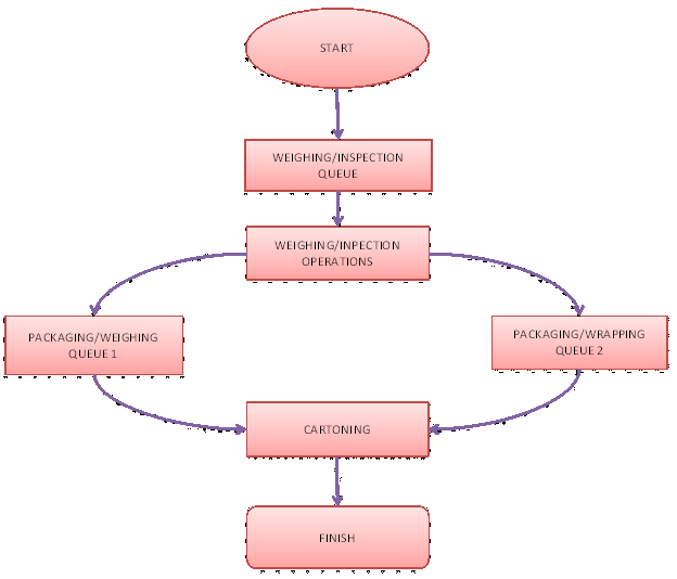
The packaging section consists of six weighing and inspection machines {m = 1, 2, 3, 4, 5, 6} and each of the machines work at the same rate and similar in specifications as well as stop time intervals, even though the frequency of stoppages are randomly distributed between all the six machines. The stoppage interval of the six weighing and inspection machines is approximately a negative exponential distribution of 240 minutes and upon stoppage the repair time range between a minimum of 15 minutes and a maximum of 20 minutes.
Fifty applications (bush press automobile parts) arrive in every 30 minutes and are buffered into a queue awaiting to be inspected and weighed by the inspection and weighing machines prior to wrapping and eventually being put into cartons. This operation takes duration of between 2 and 10 minutes for each application (bush press automobile parts) meaning the process a uniform cycle time of between 2 and 10 minutes.
Want help to write your Essay or Assignments? Click here
From the inspection and weighing machines the applications (bush press automobile parts) are directed into another queue of the packaging or wrapping machines where they are wrapped before being put into cartons and then taken to the warehouse for storage awaiting dispatch to the market. There are two packaging or wrapping machines arranged in a conveyor format each with a capacity of 1000 applications (bush press automobile parts) meaning the total buffering capacity of the wrapping machines is 2000.
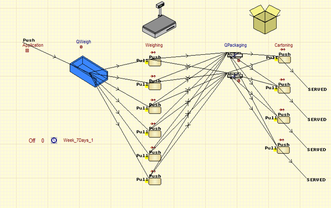
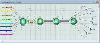
Subsequently, the wrapped applications (bush press automobile parts) are directed to the cartoning machines which package them into cartons. There are four cartoning machines {m = 1, 2, 3, 4} which operate effectively throughout unless during planned maintenance shutdown and during this period the production is temporarily stopped or a contingency plan is implemented in case there is a high demand. This operation takes duration of between 2 and 15 minutes for each application (bush press automobile parts) meaning the process a uniform cycle time of between 2 and 15 minutes. The packaging area operations are illustrated in the conceptual model shown below:
Figure 1: Conceptual Model
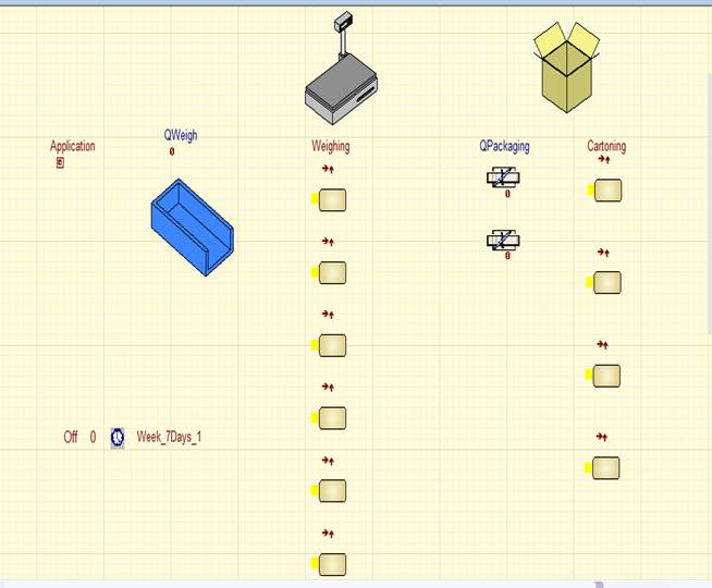
A combination of the conceptual model simulation modelling information with the shifts, sub-shifts as well as shifts and sub-shifts breaks the outcome of running the simulation model based on the specifies rules both the model outcome without element flow illustrations and the one with element flow illustrations are shown in Figure 2 and Figure 3 shown below respectively:
Figure 2: Final Model without Elements Flow
Figure 3: Final Model with Elements Flow
The Data Collection and Input Modelling Process
Data collection
According to Ballakur & Steudel (2007) data collection constitutes the most imperative part of the entire despite of it being a very daunting, frustrating as well as time consuming task mainly because it sets the stage for the simulation project as a whole. As a result, the time needed to develop the simulation model may significantly vary based on the extent of quality and quantifiable data that should be collected prior to beginning the actual simulation.
Banks and Carson (2004) argued that even when the validity of a simulation model structure has been confirmed, if collected data is inputted incorrectly collected, followed by inappropriate analysis, the resulting simulation output will not be a representation of the actual environment, and will provide misleading and possibly damaging information. In this group project, the data was not fully available and the collected data was supplemented by some tentative estimation to ensure significant variation was not witnessed between the actual production scenario and the simulation scenario.
In particular, the data was collected about Nissan’s packaging section processes specifically on the arrival profile, shifts and sub-shifts, activity cycle times, capacity of queues, as well as stoppages of the inspection and weighing machines for the bush press body parts from the assembling line.
Arrival Profile
Time
Length
Volume
1
8:00
30
50
2
8:30
30
50
3
9:00
30
50
4
9:30
30
50
5
10:00
30
50
6
10:30
30
50
7
11:00
30
50
8
11:30
30
50
9
12:00
30
50
10
12:30
30
50
11
1:00
30
50
12
1:30
30
50
13
2:00
30
50
14
2:30
30
50
15
3:00
30
50
16
3:30
30
50
17
4:00
30
50
18
4:30
30
50
19
5:00
30
50
20
5:30
30
50
Day shifts
Period Type
Working Period
Rest Time
Overtime
Subshift Name
Total
1
Subshift
480
960
0
Day subshift
1440
2
Subshift
480
960
0
Day subshift
1440
3
Subshift
480
960
0
Day subshift
1440
4
Subshift
480
960
0
Day subshift
1440
5
Subshift
480
960
0
Day subshift
1440
6
Subshift
240
1200
0
Day subshift
1440
7
Subshift
240
1200
0
Day subshift
1440
Total
2880
7200
0
10080
Breaks during Shifts
Period Type
Working Time
Rest Time
Overtime
Subshift Name
Total
1
Period
180
15
0
195
2
Period
105
60
0
165
3
Period
120
15
0
135
4
Period
75
870
0
945
Total
480
960
0
1440
Stoppages of the Final Inspection and Weighing Machines
Final Inspection and Weighing Machine Operation Stoppages
Busy Time
Negative exponential distribution of 240 minutes
Repair Time
A uniform distribution of 15 minutes minimum and 20 minutes maximum
Simulation rules were also considered whereby all input rules were set to be push and the output rules were set as pull i.e. the default rules in the simulation model settings. As a result, the simulation rules were used to connect the flow of elements through the simulation model from start to finish.
Want help to write your Essay or Assignments? Click here
Want help to write your Essay or Assignments? Click here
Tensile Testing
Summary
Tensile testing is undeniably the most imperative experimental method that is used in determining the characteristics or properties of various materials for the purpose of predicting their behaviours as well as how they would respond to tension in their real world engineering applications. The specific properties of material that are determined through tensile test include maximum elongation, ultimate tensile strength as well as reduction in area.
The material properties are imperative in the selection of materials for mechanical design. In this lab experiment, a tensile tester was used to determine tensile properties of specimens of three materials namely duralumin, PVC and aluminium.
From the obtained tensile test results, duralumin properties including tensile strength (N/m2), yield stress (N/m2) and % elongation were 0.054 N/m2, 1.29231 N/m2 and 29.23 % respectively. In addition, those of PVC were 0.928 N/m2, 37.73585 N/m2 and 37.74 % for tensile strength (N/m2), yield stress (N/m2) and % elongation respectively; whereas those of aluminium were 0.083 N/m2, 0.65789 N/m2 and 65.79 % for tensile strength (N/m2), yield stress (N/m2) and % elongation respectively.
These properties show that both duralumin and aluminium are ductile and tough compared to PVC which indicate stiffness properties. These properties are further illustrated in the stress-strain plots of each material. In conclusion, the tensile test results obtained from this lab experiment are useful in determining tensile properties of materials as well as providing valuable information concerning not only the material’s mechanical behaviours but also its engineering performance.
Want help to write your Essay or Assignments? Click here
Introduction
The determination of the mechanical properties or characteristics of materials is done by performing laboratory experiments that are carefully designed so that they can be replicated under the same service conditions as nearly as possible. In real world applications of materials in mechanical engineering, there is involvement of myriad of factors in the determination of the nature in which application of loads can be done on a material (Czichos, 2006).
According to Ashby (2006) tensile testing is a fundamental test in material science where controlled tension is subjected to a sample until failure, and the obtained results often used for quality control and selection of materials for application. According to Hibbeler (2004), the specific properties of material that are determined through tensile test include maximum elongation, ultimate tensile strength as well as reduction in area. The material properties are imperative in the selection of materials for mechanical design (Davis, 2004).
Tensile testing is without any doubt the experimental method that is used in determining the characteristics of various mechanical materials with an intention of predicting the behaviours of such materials and how they would respond to tension in their real world engineering applications (Czichos, 2006).
The main objective of this experiment is to conduct an experimental tensile testing on various mechanical materials, i.e. duralumin, aluminium and PVC in order to determine and compare their characteristics, which can be used to predict their particular behaviours in real world engineering applications. The other main objective is to plot graphs describing the characteristics or properties of these materials as obtained in the tensile testing results.
As a result, graphs depicting the properties of these materials shall be plotted by stretching the samples of each of provided materials of known dimensions to destruction upon applying force subsequent to noting the ensuing elongation.
Thus, tensile test results obtained in this lab has many benefits because they enable a stress-strain diagram to be obtained, which is useful in determining the tensile properties of materials as well as providing valuable information concerning not only the material’s mechanical behaviours but also its engineering performance (Hibbeler, 2004).
Want help to write your Essay or Assignments? Click here
Theory
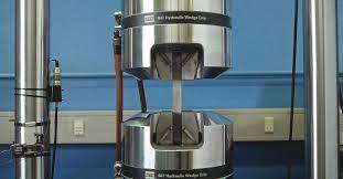
The topic covered in this lab experiment is focused to testing of tensile properties of various materials that have different compositions. Figure 1 illustrated below shows a machine used in tensile testing that resembles the one used during the laboratory experiment session. Tensile test is a destructive in nature, in which an axial is subjected to a sample of the material to be tested, and the specimen has to be of a standard shape as well as dimensions.
During a typical procedure for a tensile testing laboratory experiment, a specimen that dog-bone shaped is usually gripped at the top and bottom of the tensile machine on its two ends prior to pulling so that elongation occurs at a determined rate that is controlled up to its breakpoint (Hibbeler, 2004). Tensile testers vary mainly on the basis of pulling rate and maximum load, and their setup during an experiment could be varied for the purpose of mechanical testing of different materials through tensile test (Czichos, 2006).
Figure 1: Tensile test 1 (A photograph of a tensile machine)
For analytical purposes, stress (σ) vs. strain (ε) is plotted from a tensile test experiment results, and this can be done either manually or automatically (Czichos, 2006). In the metric system, the usual measure for stress is Pa or N/m2, such that 1 Pa = 1 N/m2. From the laboratory experiment, the calculation of stress values is done through division applied force (F) by the cross-sectional area (A) of the machine, which is measured before the experiment is run (Hibbeler, 2004). Equation 1 and 2 below are used to calculate stress and strain values respectively.
Want help to write your Essay or Assignments? Click here
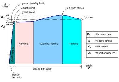
A typical stress-strain plot would look like figure 2 below, which is an example of a generalised and typical representation of a stress-strain curve for ductile metal materials (Davis, 2004). Figure 2 below indicates that the curve has four parts: elastic region, yielding region, strain hardening region and necking region, which occur in almost all materials except the strain hardening region commonly occurring in metallic materials (Czichos, 2006).
In theory, even without the specimen’s cross-sectional area measurement during the tensile testing lab experiment, it is possible to construct a “true” stress-strain curve based on the assumption that there is constant amount of the material. Using this concept, it is possible to calculate both the true strain (εT) and the true stress (σT) using Equation 3 and Equation 4, respectively.
Want help to write your Essay or Assignments? Click here
In the curve shown in Figure 2 above, the linear region, which is known as the elastic region depicts the region of the curve where the behaviour of the material is elastic. Equation 5 can be used to calculate the slope of the curve, which is an intrinsic property and is a constant of a material referred to as the elastic modulus (E). Its SI unit is Pascal (Pa).
Figure 3 shown below illustrates a typical stress-strain curve plot, and it shows that different materials, both metals and polymers portray varied properties under tension, which determines their greatest extent of deformation or ductility before fracture whereby some have very steep or relatively gentle elastic moduli.
According to Hibbeler (2004), mechanical properties of both metals and polymers are generally dependent on their molecular weights, extent of crystallinity, as well as glass transition temperature, Tg. For instance, if materials under consideration are highly crystalline and with a Tg higher than room temperature usually tend to be brittle, and vice versa (Davis, 2004).
On the other hand, when semi-crystalline polymers or materials are subjected to tensile testing, there will be an alignment of the amorphous chains usually evident for translucent and transparent materials, which have a tendency of becoming opaque after they turn crystalline.
The stress-strain curve is used to give Young’s Modulus based on the run and rise of the slope, which is calculated similar to the gradient of a curve within the yield strength range prior to the material entering the ultimate strength phase subsequent to fracturing (Ashby, 2006)
Figure 3: A typical stress-strain curve plot
Equipment and Procedure
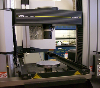
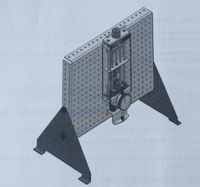
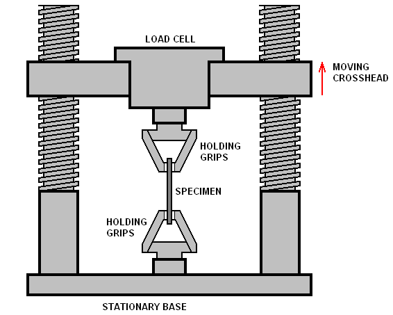
Prior to beginning the experiment, the supplied guidance notes were carefully read after which the experiment setup of the tensile testing machine was confirmed to be alright. A photograph of the experiment is shown in Figure 4 below. Consequently, Figure 5 that follows is a detailed schematic diagram of a tensile testing machine showing the main parts.
Holding grips are used both at the top and bottom to hold the specimen in place firmly; load cell is used to provide the required weight depending on the sample material’s load range and sensitivity. In addition, the stationary base is used to ensure stability of the machine, while moving crosshead is used to adjust the load cell subjected to the material.
Figure 4: Experiment SetupPhotograph of a Tensile Testing Machine
Figure 5: Detailed Schematic of a Tensile Testing Machine
Prior to starting the tensile test the safety guard was fitted followed by the selection of the specimen, which was then followed by the use of Dial Calliper for the width and thickness measurement of the specimen at gauge length as well as the cross-sectional area was determined.
The initial length of the specimen was measured and recorded or reference. The specimen was then fitted to the Tensile Tester followed by setting to zero the Dial Indicator, and the readings obtained for each specimen on the Vertical Scale were noted. Then the Load Nut was turned clockwise gradually in steps of 0.2 mm up to the length of 5 mm in a serial manner, and then followed by larger steps of 1 mm and 10 mm until the specimen broke.
The applied rate was kept consistent, i.e. 5 seconds were taken between each 0.2 mm of Load Nut turning followed by another 5 seconds for the readings to be recorded. The Dial Indicator value was recorded at each step, and for PVC specimen, this was done immediately after the load was change in order to obtain consistent results.
Want help to write your Essay or Assignments? Click here
The specimen elongation was checked by removing the specimen from the tensile tester and the broken ends were pushed together in order to measure the final length. The next step was conversion of the readings of the Dial Indicator into force values. The extension of the specimens at each step was determined by subtracting the readings of the Dial Indicator from those of the Load Nut movement.
The obtained values of force and extension were consequently converted to stress as well as nominal strain values, which were subsequently plotted on the chart paper for each specimen, i.e. the steel, PVC and alloy. The yield points and tensile strengths for each specimen were noted from the charts. Finally, the elastic region gradients for each specimen were determined for subsequent comparison of the stiffness of the materials.
Results and Discussion
The tensile testing results are shown in table 1 below where the results of the three specimens are illustrated on properties such as force, extension, strain and stress. In addition, tensile strength, yield stress and percentage of elongation are calculated and included in the table for duralumin, PVC and aluminium respectively. Furthermore, the stress-strain curves for each of the specimens are plotted to illustrate the relationships between the two properties in Figures 6, 7 and 8.
Table 1: Data collected from experiment 1
Duralumin
PVC
Aluminium
Load Nut movement (mm)
Dial Indicator (mm)
Force (N)
Extension (mm)
Stress σ N/m2
Nominal Strain ԑ
Load Nut movement (mm)
Dial Indicator (mm)
Force (N)
Extension (mm)
Stress σ N/m2
Nominal Strain ԑ
Load Nut movement (mm)
Dial Indicator (mm)
Force (N)
Extension (mm)
Stress σ N/m2
Nominal Strain ԑ
0
0
0
0
0
0
0
0
0
0
0
0
0
0
0
0
0
0
0.2
1.65
0.2
-1.45
0.12121
-0.8787
0.2
0.36
0.2
-0.16
0.55556
-0.44444
0.2
0.62
0.2
-0.42
0.32258
-0.67742
0.4
1.865
0.4
-1.465
0.21448
-0.7855
0.4
0.495
0.4
-0.095
0.80808
-0.19192
0.4
0.98
0.4
-0.58
0.40816
-0.59184
0.6
1.91
0.6
-1.31
0.31414
-0.6858
0.6
0.52
0.6
0.08
1.15385
0.15385
0.6
1.29
0.6
-0.69
0.46512
-0.53488
0.8
1.96
0.8
-1.16
0.40816
-0.5918
0.8
0.63
0.8
0.17
1.26984
0.26984
0.8
1.41
0.8
-0.61
0.56738
-0.43262
1
2.09
1
-1.09
0.47847
-0.5215
1
0.61
1
0.61
1.63934
1
1
1.52
1
-0.52
0.65789
-1
1.2
2.14
1.2
-0.94
0.56075
-0.4392
1.2
0.59
1.2
0.61
2.0339
1.0339
1.2
1.4
2.28
1.4
-0.88
0.61404
-0.3859
1.4
0.58
1.4
0.82
2.41379
1.41379
1.4
1.6
2.44
1.6
-0.84
0.65574
-0.3442
1.6
0.56
1.6
1.04
2.85714
1.85714
1.6
1.8
2.55
1.8
-0.75
0.70588
-0.2941
1.8
0.56
1.8
1.24
3.21429
2.21429
1.8
2
2.68
2
-0.68
0.74627
-0.2537
2
0.55
2
1.45
3.63636
2.63636
2
2.2
2.81
2.2
-0.61
0.78292
-0.2170
2.2
0.53
2.2
1.67
4.1509
3.15094
2.2
2.4
2.89
2.4
-0.49
0.8304
-0.1695
2.4
0.53
2.4
1.87
4.5283
3.5283
2.4
2.6
2.92
2.6
-0.32
0.8904
-0.109
2.6
0.52
2.6
2.08
5
4
2.6
2.8
2.98
2.8
-0.18
0.9396
-0.060
2.8
0.51
2.8
2.29
5.4902
4.4902
2.8
3
3.1
3
0.1
0.9677
0.0322
3
0.5
3
2.5
6
5
3
3.2
3.11
3.2
0.09
1.0289
0.0289
3.2
0.5
3.2
2.7
6.4
5.4
3.2
3.4
3.16
3.4
0.24
1.0759
0.0759
3.4
0.49
3.4
2.91
6.9387
5.93878
3.4
3.6
3.19
3.6
0.41
1.1285
0.1285
3.6
0.49
3.6
3.11
7.3469
6.34694
3.6
3.8
3.22
3.8
0.58
1.1801
0.1801
3.8
0.48
3.8
3.32
7.9166
6.91667
3.8
4
3.23
4
0.77
1.2383
0.2383
4
0.47
4
3.53
8.5106
7.51064
4
4.2
3.25
4.2
0.95
1.2923
0.2923
4.2
0.46
4.2
3.74
9.1304
8.13043
4.2
4.4
4.4
0.46
4.4
3.94
9.5652
8.56522
4.4
4.6
4.6
0.45
4.6
4.555
10.222
10.12222
4.6
4.8
4.8
0.41
4.8
4.39
11.707
10.70732
4.8
5
5
0.36
5
4.64
13.888
12.88889
5
6
6
0.33
6
5.67
18.181
17.18182
6
7
7
0.29
7
6.71
24.13
23.13793
7
8
8
0.29
8
7.71
27.586
26.58621
8
9
9
0.28
9
8.72
32.142
31.14286
9
10
10
0.265
10
9.735
37.73
36.73585
10
Tensile Strength (N/m2): 0.054 N/m2
Tensile Strength (N/m2):0.928 N/m2
Tensile Strength (N/m2): 0.083 N/m2
Yield Stress (N/m2): 1.29231 N/m2
Yield Stress (N/m2): 37.73585 N/m2
Yield Stress (N/m2): 0.65789 N/m2
% Elongation: 29.23%
% Elongation: 37.74%
% Elongation: 65.79%
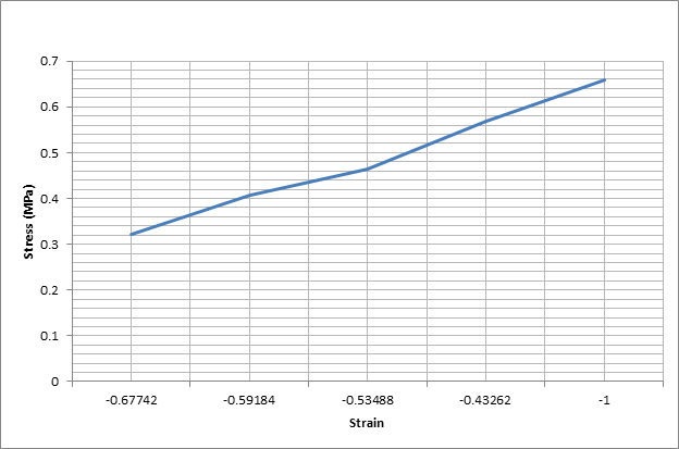
The figures below show the stress-strain plots for each of the specimens tested;
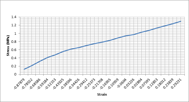
Figure 6: Duralumin Stress-strain plot
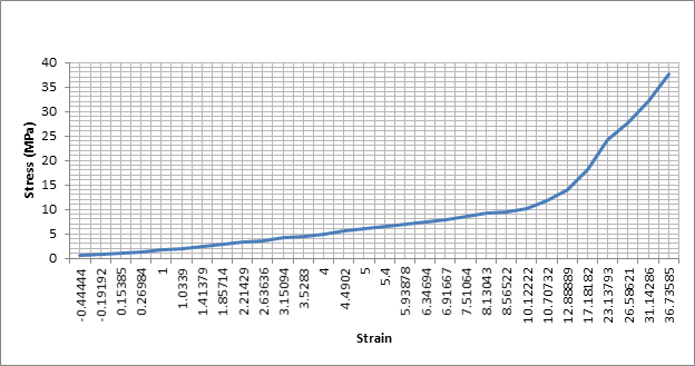
Figure 7: PVC Stress-strain plot
Figure 8: Aluminium stress-strain plot
From the tensile test results shown in table 1 above, duralumin properties including tensile strength (N/m2), yield stress (N/m2) and % elongation were 0.054 N/m2, 1.29231 N/m2 and 29.23 % respectively. In addition, those of PVC were 0.928 N/m2, 37.73585 N/m2 and 37.74 % for tensile strength (N/m2), yield stress (N/m2) and % elongation respectively; whereas those of aluminium were 0.083 N/m2, 0.65789 N/m2 and 65.79 % for tensile strength (N/m2), yield stress (N/m2) and % elongation respectively.
These characteristics show that both duralumin and aluminium are ductile and tough compared to PVC which indicate stiffness properties. These properties are further illustrated in the graphs.
Two specimen of the materials, i.e. duralumin and aluminium produced gradients that are relatively the same in their elastic region mainly because they are both metals even though one is a pure metal while the other one is an alloy. The reason why there is a significant difference between tensile properties of the two materials and PVC (which is a polythene polymer) is that, the chemical compositions are totally different hence making them to behave differently under tension (Davis, 2004).
Constant temperature and force application rate are very important for PVC specimens because it is composed of polymers, which easily change even with slight variations of temperature or force and this makes it imperative to ensure that both temperature and force application rate are maintained constant in order to obtain consistent results (Czichos, 2006).
Want help to write your Essay or Assignments? Click here
Some of the important shortcomings of the experimental apparatus is that, when large forces are been exerted there is a likelihood of the equipment to flex resulting to some extent of displacement (Tarr, n.d.). This machine’s displacement is often mistakenly read and recorded as a displacement of the specimen, and can lead to false results. To address this challenge, the tensile machine should be firmly held on the bench to ensure that no flexing occurs when large forces are applied on the specimens (Ashby, 2006).
Conclusion and Recommendations
By undertaking this lab experiment, I have learned a lot about the concept of tensile testing and my understanding on the same has significantly improved. For instance, I have gained more insights on how tensile properties differ between materials based on their chemical composition. In particular, the tensile properties of the three materials including tensile strength (N/m2), yield stress (N/m2) and % elongation varied considerably, especially between PVC and the other two materials (duralumin and aluminium) mainly due to their composition differences.
The specific aspects of the procedure of this lab experiment that contributed immensely to my learning was about the extension or elongation variations observed between materials before they broke, whereby significant difference was observed between metal specimens and PVC specimens. Prior to doing the lab experiment I had difficulties in comprehending how the tensile testing concept is used in choosing materials for mechanical engineering applications.
However, after the lab experiment my difficulties were alleviated by understanding how tensile strength, ductility, stiffness and brittleness of materials can be determined through this concept enabling selection of appropriate materials. The lessons learned in this lab experiment can be applied in future by extending acquired experience and skills to other mechanical testing such as compression, tear and shear.
References
Ashby, M. (2006) Engineering Materials 1: An Introduction to Properties, Applications and Design. 3rd ed. New York, NY: Butterworth-Heinemann.
Want help to write your Essay or Assignments? Click here
Manufacturing Process Simulation Model Using WITNESS Software
Introduction
Nowadays, simulation models which are designed based on varied simulation software have gained wide utilisation in the evaluation of different aspects of manufacturing systems. In this group project, the WITNESS software will be applied to simulate the packaging process of an automobile manufacturing assembly line in a production company that is cost-conscious and interested in introducing a new product (Ceric, 2014). Technically, line balancing through optimization of the manufacturing and packing processes is one of the components of improving production efficiency in manufacturing industries.
As a result, the concept of manufacturing process optimization itself is based on the fact that everyone as well as the machines is working together in a balance in a manner that the amount of work carried out by staff or machines with similar capacities is the same, and the variation is smoothed to ensure that no particular element of the production process overburden (Carrie, 2014). This is aimed at ensuring that waiting time for work is alleviated and therefore it is carried out in a well organized and single piece flow.
Want help to write your Essay or Assignments? Click here
The Description of the System that is going to be Modelled and the Problem(s)
Inadequate software experimentation irrespective of adequate modelling is usually among the leading causes of poor decisions in manufacturing companies and often gives detrimental results, especially when there is involvement of financial investment (Ballakur & Steudel, 2007). The group project is about a weighing and packaging process simulation model in a manufacturing company based on WITNESS software. The group project is regarding improvement of the performance of the packing area with the help of simulation model.
The automobile company produces both motor vehicles and respective motor body parts by implementing lean manufacturing system in their plant. The main objective of this simulation model based on WITNESS software is to strive to reduce congestion at the packaging area of an automobile manufacturing company’s assembly line, particularly by improving the efficiency and productivity of weighing and inspection as well as wrapping and cartoning processes through precise simulation.
For this project, our group modelled the functions or operations of the packaging area of Nissan Motor Manufacturing (UK) Limited, which was selected due to the challenges they were experiencing when the company was undertaking an aggressive expansion strategy not only in its Sunderland manufacturing plant, but also in other regions in the United Kingdom and across the world.
However, due to the limitations of the WITNESS simulation software as well as the short duration through which the project had to be completed, our group opted to settle for a section of the manufacturing process, that is, the packaging where various processes are carried out.
As a result, our group decided to focus on only some aspects of the packaging section, particularly the last stage of quality control which is the final inspection and weighing of various body parts as well as wrapping and packaging of the motor body parts in cartons. In particular, we modelled the packaging of bush press for its latest model of car known as Qashqai.
The reason why we chose this problem for the simulation model is attributable to the fact that, Nissan company was a good case of how many automobile manufacturing companies are faced my numerous challenges when it comes to addressing the challenge of space utilization and reduction of congestion not only in their packaging section, but in the entire manufacturing process as a whole even though the former is more imperative considering that, it is the last stage in the manufacturing process prior to the body parts being taken to the warehouse awaiting to be shipped overseas or transported for distribution (Lanner, 2013).
This choice was further attributed by the fact that, some data was available online in addition to the potential of making estimations that are not significantly different from the anticipated results of the actual manufacturing process. Thus, considerable data was collected concerning Nissan Motor Manufacturing Company Limited, particularly the manufacturing plant which is based in Sunderland.
This was further enhanced by making estimates that were not significantly different from the actual production process data. No particular visit was made to the actual manufacturing plant location, but quite a lot of time was spent discussing the various aspects of the manufacturing process data including the processes included in the packaging section, arrival profile of the finished body parts, shifts of employees working in the packaging section as well as the durations needed to each of the considered process for each body part.
Sometimes the packaging area may involve many activities, but in our project we specifically focused on the final inspection and weighing of the finished body parts particularly the bush press as well as the wrapping and cartoning of the bush press prior to being taken to the warehouse for storage awaiting dispatch to the market. We focused on bush press because of their peculiar nature which makes their demand extremely high in the market, especially at a time like this when Nissan Motor Manufacturing Limited was experiencing tremendous growth in its production capacity due to increased market demand.
Want help to write your Essay or Assignments? Click here
In an automobile manufacturing market which is hugely competitive, Nissan has to no option but making sure that it demonstrates superb value for money in its attempts towards securing contracts for new car models’ production (Lanner, 2013). This is attributable to the fact that these new contracts for the manufacturing of new car models can only be secured by companies that have the ability to provide the best option in manufacturing with regards to cost, delivery, and quality.
In particular, the Nissan manufacturing plant in our group project faces stiff competition not only from competitors in the market but also other Nissan plants located in UK as well as across the world. As a result, the Nissan manufacturing plant based in Sunderland is without any doubt in desperate need to make sure that there is optimization of its production processes, especially for the manufacturing of the latest Nissan’s Qashqai car model (Lanner, 2013).
This was to a significant extent motivated by the introduction of the suspension plant that was specifically installed for the manufacturing of the Qashqai model, and the company needed to succinctly understand and outline the role of this newly introduced automobile manufacturing technology (Lanner, 2013).
In addition, there was need to delve into details of the sources of congestion in the packaging section which was becoming a common phenomenon sometimes hindering smooth production flow due to lack of space for convenient and flexible manoeuvring of company employees during manufacturing processes as well as limiting storage space of finished bush press automobile body parts and delays in market delivery to meet the orders placed for finished parts.
There are also other aspects of the simulation scenario that have the potential to impact the throughput of the automobile company including number of employees, production durations, number of automobile parts that can be at a time, sources of raw materials, the market demand, technology employed in the manufacturing assembly line and packaging, size of the warehouse and many others (Fishwick, 2008).
Most of these aspects can not be easily altered without expensive changes have to be made to the company, which is mainly the reason why in this group project we are going to begin by optimizing the packaging section efficiency and performance, particularly the inspection and/or weighing as well as wrapping and cartoning processes. The WITNESS software simulation group project will be divided into five main parts.
These parts are particularly: the introduction, the role/importance of WITNESS simulation software in company manufacturing process, model build process and analysis of collected data, implementation of the simulation model as well as the improvement of the simulation model and conclusion.
The introduction part will provide basic and/or background information about simulation models in company manufacturing process and in particular emphasizing on WITNESS simulation software on which this project will be based. The purposes for which software based simulation models have been used in manufacturing will be discussed in this part.
In addition, the place of simulation in contemporary manufacturing processes will also be discussed together with the progressive use and progress made in computer simulation models to simulate various manufacturing systems and/or processes for reduction of costs and improved productivity. The essence of the wide usage of simulation in company manufacturing processes as a stylish, flexible and contemporary management tool will be highlighted.
Want help to write your Essay or Assignments? Click here
The second part will discuss the role of simulation in manufacturing process. An emphasis will be put on reviewing literature to provide evidence on the use of simulation in manufacturing process. In this part, focus will be on production aspect of the manufacturing process and how simulation modelling has been used to facilitate making of decisions and its imperativeness in solving production management problems.
The third part will present the simulation model building process with an emphasis on elucidating how the simulation model will be executed. This will be done simultaneously with collection of data and analysis of the results of the simulation model in order to identify the bottlenecks of the manufacturing process or production system as well as the underlying issues that cause the problems.
The fourth part will be concerned with the implementation of the developed simulation model based on WITNESS software in order to identify, verify and validate the simulation model results. Finally, the last part will discuss the modifications if necessary that will be made on the developed simulation model in order to improve the manufacturing process for increased total output (productivity) and maximization of inventory of products. Lastly, recommendations and a conclusion on the simulation project and the developed simulation model based on WITNESS software will be provided.
The Conceptual Model
The packaging section consists of six weighing and inspection machines {m = 1, 2, 3, 4, 5, 6} and each of the machines work at the same rate and similar in specifications as well as stop time intervals, even though the frequency of stoppages are randomly distributed between all the six machines. The stoppage interval of the six weighing and inspection machines is approximately a negative exponential distribution of 240 minutes and upon stoppage the repair time range between a minimum of 15 minutes and a maximum of 20 minutes.
Fifty applications (bush press automobile parts) arrive in every 30 minutes and are buffered into a queue awaiting to be inspected and weighed by the inspection and weighing machines prior to wrapping and eventually being put into cartons. This operation takes duration of between 2 and 10 minutes for each application (bush press automobile parts) meaning the process a uniform cycle time of between 2 and 10 minutes.
Want help to write your Essay or Assignments? Click here
From the inspection and weighing machines the applications (bush press automobile parts) are directed into another queue of the packaging or wrapping machines where they are wrapped before being put into cartons and then taken to the warehouse for storage awaiting dispatch to the market. There are two packaging or wrapping machines arranged in a conveyor format each with a capacity of 1000 applications (bush press automobile parts) meaning the total buffering capacity of the wrapping machines is 2000.
Subsequently, the wrapped applications (bush press automobile parts) are directed to the cartoning machines which package them into cartons. There are four cartoning machines {m = 1, 2, 3, 4} which operate effectively throughout unless during planned maintenance shutdown and during this period the production is temporarily stopped or a contingency plan is implemented in case there is a high demand. This operation takes duration of between 2 and 15 minutes for each application (bush press automobile parts) meaning the process a uniform cycle time of between 2 and 15 minutes. The packaging area operations are illustrated in the conceptual model shown below:
Figure 1: Conceptual Model
A combination of the conceptual model simulation modelling information with the shifts, sub-shifts as well as shifts and sub-shifts breaks the outcome of running the simulation model based on the specifies rules both the model outcome without element flow illustrations and the one with element flow illustrations are shown in Figure 2 and Figure 3 shown below respectively:
Figure 2: Final Model without Elements Flow
Figure 3: Final Model with Elements Flow
The Data Collection and Input Modelling Process
Data collection
According to Ballakur & Steudel (2007) data collection constitutes the most imperative part of the entire despite of it being a very daunting, frustrating as well as time consuming task mainly because it sets the stage for the simulation project as a whole. As a result, the time needed to develop the simulation model may significantly vary based on the extent of quality and quantifiable data that should be collected prior to beginning the actual simulation.
Banks and Carson (2004) argued that even when the validity of a simulation model structure has been confirmed, if collected data is inputted incorrectly collected, followed by inappropriate analysis, the resulting simulation output will not be a representation of the actual environment, and will provide misleading and possibly damaging information. In this group project, the data was not fully available and the collected data was supplemented by some tentative estimation to ensure significant variation was not witnessed between the actual production scenario and the simulation scenario.
In particular, the data was collected about Nissan’s packaging section processes specifically on the arrival profile, shifts and sub-shifts, activity cycle times, capacity of queues, as well as stoppages of the inspection and weighing machines for the bush press body parts from the assembling line.
Arrival Profile
Time
Length
Volume
1
8:00
30
50
2
8:30
30
50
3
9:00
30
50
4
9:30
30
50
5
10:00
30
50
6
10:30
30
50
7
11:00
30
50
8
11:30
30
50
9
12:00
30
50
10
12:30
30
50
11
1:00
30
50
12
1:30
30
50
13
2:00
30
50
14
2:30
30
50
15
3:00
30
50
16
3:30
30
50
17
4:00
30
50
18
4:30
30
50
19
5:00
30
50
20
5:30
30
50
Day shifts
Period Type
Working Period
Rest Time
Overtime
Subshift Name
Total
1
Subshift
480
960
0
Day subshift
1440
2
Subshift
480
960
0
Day subshift
1440
3
Subshift
480
960
0
Day subshift
1440
4
Subshift
480
960
0
Day subshift
1440
5
Subshift
480
960
0
Day subshift
1440
6
Subshift
240
1200
0
Day subshift
1440
7
Subshift
240
1200
0
Day subshift
1440
Total
2880
7200
0
10080
Breaks during Shifts
Period Type
Working Time
Rest Time
Overtime
Subshift Name
Total
1
Period
180
15
0
195
2
Period
105
60
0
165
3
Period
120
15
0
135
4
Period
75
870
0
945
Total
480
960
0
1440
Stoppages of the Final Inspection and Weighing Machines
Final Inspection and Weighing Machine Operation Stoppages
Busy Time
Negative exponential distribution of 240 minutes
Repair Time
A uniform distribution of 15 minutes minimum and 20 minutes maximum
Simulation rules were also considered whereby all input rules were set to be push and the output rules were set as pull i.e. the default rules in the simulation model settings. As a result, the simulation rules were used to connect the flow of elements through the simulation model from start to finish.
Want help to write your Essay or Assignments? Click here
Want help to write your Essay or Assignments? Click here
CHILDREN BCI EXPERIENTIAL IMPACT ON USABILITY ENGINEERING OF COGNITIVE APPLICATIONS
1.1 Emotional importance in usability of cognitive application
1.1.1 Children Cognitive Application
Understanding the emotions of human beings is important as it can help to tell how people usually think. To properly study the human emotions, then children aged 4-6 years old can be used in the study. Children in this age bracket are particularly important for use in the study since they cannot tell what really emotion or feeling is from the things they interact with (Ekman, 1992). In essence, the main aim of this study is to delve into the impact of the emotional of children in usability of technologies designed for children aged from 4 to 6 years old. The thesis also seeks to evaluate the usability of cognitive application – based on the children emotions at three stages in the software development process.
1.1.2 Brain Computer Interfaces (BCI) technology
Brain computer interface (BCI) headset technology would be used as a pathway between human and computer, and it will determine the emotion of the user – such as engagement/boredom, frustration, meditation, instantaneous excitement, and long-term excitement – to really understand the emotion of the target user and to predicate the effectiveness of these emotions in usability engineering of this game based on tree cycles testing. From a usability perspective, the researcher is interested in the following aspects:
(i) Effectiveness: the relative effectiveness of different mnemonic actions of children to reach an intended goal;
(ii) efficiency: time taken to complete tasks related to allocation of resources and usage; and
(iii) satisfaction: measures emotional of children reaction by the Emotiv Epoc headset in different emotions such as instantaneous excitement, long term excitement, meditation, engagement and frustration.
This research is particularly important because of the outcomes that would come out of it: the findings will reveal the children emotional impact in usability engineering of cognitive applications with the use of BCI headset. Moreover, the findings will reveal the emotional reactions of children, the usability engineering methods, and the brain-computer interaction technology; the results will also reveal what the suitable interactive design of memory games for children is; and the extent to which the designed game meet the usability requirements by expert review evaluation and heuristic inspection of experts.
Emotions are of great importance in enhancing or improving any system interaction (Brave & Nass, 2003). Previously, systems used to be developed aesthetically and with no regard or response to the emotional influence which they possessed (Papanek, 1985). In addition, system designers have reported that in the past, interactions with technology, computers in particular, were sterile and unemotional (Brave & Nass, 2003).
Nevertheless, design philosophers, scholars, neuroscientists and psychologists have pointed out that nowadays, emotion plays an integral role in how people interact with technology, which include computers as well as the interfaces that have developed to interact by means of this medium. According to (McCarthy & Wright, 2004), designers of interfaces and interactive systems need to recognize and centralize the emotional-volitional nature of any system.
In addition, it is important that designers understand they do not design emotions, but instead they design for the optimum experience that results from personal interaction with the objects experienced in everyday life. It is worth mentioning that an extensive array of emotions play influential roles in almost every goal-oriented activity (Brave & Nass, 2003).
Emotions are essentially built from plain reactions which easily promote the survival of an organism, hence could easily succeed in evolution (Damasio, 2001). Interestingly enough, (Damasio, 2001) gave a description about the ordering of feelings and emotions. Damasio (2001) pointed out that emotions managed to withstand the evolution test. He added that first, human beings have emotions, and then feelings come second after emotions given that evolution initially came up with emotions and later on feelings followed (Damasio, 2001).
In general, human beings ultimately concern themselves with emotions, those which are made public. Emotions are actions that take place mainly in the public as they are visible to other people considering that they occur on a person’s voice, face, or even in certain conducts. Conversely, feelings of a person are normally concealed, like all mental images necessarily are, and are hidden to anyone save for their owner, the most private property of the organism in whose brain they take place (Damasio, 2001).
Emotion is one of the integral elements that are involved in education and learning (Parkinson, 1996). It affects a person’s decision making, communication and even a person’s capacity to learn. Parkinson (1996) pointed out that emotions influence the decisions that individuals make, how effectively they learn and the way they communicate with other people. Psychologists define emotion as a disorganized, intuitive response, which is caused by a lack of effective adjustment (Cannon, 1927; Schachter & Singer, 1962).
Valence is understood as the amount of negativity or positivity that an individual feels toward something. Conversely, arousal is considered as what gets the attention of an individual. In the field of computing, emotion is integral considering that it has the potential of influencing the effectiveness of learning (McCarthy & Wright, 2004). In this research study, the researcher will look into the kinds of situations which bring about emotions within a learning environment.
As such, in this project, the researcher proposes to utilize an electroencephalography (EEG) device known as the Emotiv EPOC – as conducted in the Software and Knowledge Engineering Research Group (SKERG) at King Saud University – to sense or perceive the emotions of a user through brainwaves in cognitive application game. This will allow the researcher to determine positive or negative emotional impact of this game on children and to establish and understand the usability of these kinds of cognitive applications in childhood.
EEG is essentially an electrophysiological monitoring technique for recording the brain’s electrical activity. This monitoring method is usually non-invasive as the electrodes are placed along the scalp. In specific applications however, invasive electrodes are at times utilized (Tatum, 2014). EEG measures fluctuations of voltage that result from ionic current in the brain’s neurons. Emotiv EPOC – developed by Emotiv Systems – is a neuroheadset which lets the players to control game-play with their emotions, expressions and even their thoughts. It is worth mentioning that the Emotiv EPOC, as Shende (2008) pointed out, is an innovative and pioneering high-fidelity Brain-Computer Interface device for the video game market.
The neuroheadset itself is an easy-to-utilize, glossy and lightweight wireless device that features a number of sensors which are capable of detecting conscious thoughts, expressions, as well as non-conscious emotions basing upon electrical signals around the person’s brain (Shende, 2008). The technology basically processes these signals, allowing the players to be able to control the actions or expressions of their in-game character and influence game-play with the use of their emotions, expressions and thoughts.
The Emotic EPOC can non-invasively detect brain activity with the use of EEG, a measure of brain waves, through external sensors all along the individual’s scalp which detect the electrical bustle in different areas of the furrowed surface of the cortex of the brain, a section which is responsible for handling higher-order thoughts (Sergo, 2008).
The Emotiv EPOC can detect in excess of thirty dissimilar emotions, expressions as well as actions including emotional detections like frustration, exctitement, immersion, tension and meditation; facial expressions like anger/eyebrows furrowed, wink, shock/eyebrows raised, wink, smirk, grimace/clenched teeth, horizontal eye movement, and smile; and cognitive actions like rotate, drop, push, lift, pull on 6 dissimilar axis (Shende, 2008). Owing to these detections, the player enjoys a more lifelike, immersive experience.
Want help to write your Essay or Assignments? Click here
1.1.3 Software Usability Engineering
Emotions, as Parkinson (1996) pointed out, are one of the most important factors for creating highly developed educational systems that are adaptive to the needs of the user. Emotions are vital in a lot of areas of learning including creative thinking, motivation, concentration, and even inspiration. A big part of the presently available educational systems do not consider the effects which the emotions of a user could really have on their learning. As such, this study will improve the usability of user interfaces by applying the tree cycle to measure the user’s emotion in each experiment.
Usability Engineering (UE) is understood as the methodical approach that is used to improve the usability of user interfaces by applying various established techniques during the system development lifecycle (SDLC) (Nielsen, 1993). Five qualities of usability have been identified by (Nielsen, 1993), which include efficient to utilize, easy to learn, error prevention, easy to remember, and satisfying.
As per the standard document ISO 9241-11, usability should cover 3 important things: satisfaction, efficiency and effectiveness. Usability is essentially defined as the degree to which a product could be utilized by specific users to attain specific objectives with satisfaction, efficiency, and effectiveness within a specific context of use.
Satisfaction: this encompasses positive emotions, attitudes and comfort that rise from the utilization of a given service, product or system. Attitudes comprise the degree to which the expectations of the users are attained. An individual user’s satisfaction is a part of his or her experience. This measure of usability is measured using a brief questionnaire basing upon Lewis (1991).
Efficiency: according to ISO 9241, efficiency is defined as the total resources that are used up in a given task. It is the relationship between the outcome attained and the resources utilized. This measure of usability is measured through task times. The metrics of efficiency include the number of keystrokes or clicks which are needed or the total time on task. In general, the task needs to be defined from the perspective of the user and not as a single, granular interaction (Nielsen, 1993).
Navigation design aspects for instance links, menus, keyboard shortcuts, in addition to other buttons have an impact on efficiency. When the designer designs them very well, with actions that are expressed clearly, then less amount of effort and time would be required for users to make action and navigation choices. All in all, making the correct choices for efficient utilization of the software is contingent upon an understanding of the users and the way users prefer working.
Effectiveness: this is understood as the completeness, accurateness, and lack of negative outcomes with which the user achieves specific goals (Lewis, 1991). Effectiveness is established by examining whether or not the goals of the user were attained successfully and whether all work is correct. The usability measure of effectiveness is measured through the number of errors and also through task completion.
ISO 9241-11 describes how to find the information needed to consider when assessing or spelling out usability in terms of measures of user satisfaction and performance. There is explicit guidance on how to explain the context of usage of the product as well as the measures of usability.
Usability testing will be conducted to validate the research using the Emotive EPOC headset tool. The levels of effectiveness, efficiency and satisfaction will represent the usability of a cognitive application in the field; the memory game would be designed and implemented by the researcher. The results obtained would show the viably of the approach adopted to conduct a usability testing of a computer game.
1.2 Problem Definition
Emotions are crucial in improving any system interaction. Researchers have reported that emotion plays a fundamental role in the way that individuals interact with technology such as computers. Using youngsters aged 4-6-years-old, this study seeks to gain an insight into the impact of the emotional of children in usability of technologies designed for children aged from 4 to 6 years old.
The researcher will also investigate to determine the impact of these emotions in usability of this game with usability engineering by using BCI headset because this target – the 4-6 year old children – cannot tell really what they feel. The researcher proposes to employ an electroencephalography (EEG) device, the Emotiv EPOC, in detecting the emotions of a user through brainwaves in the cognitive application game to demonstrate that the emotional responses of people could actually vary.
The problem is to understand the impact of children’s emotion in the cognitive application game: children aged 4-6 years. This is significant considering that children cannot really explain their emotion. Therefore this research would help to determine the impact from the children’s minds rather than through conversation since these children cannot actually give good explanation of their young age. Moreover, the researcher will determine how this cognitive application game can be used to improve learning in children rather than just using this innovative technology without any benefits to the users.
1.3 Research Scope
Target user
Target users are basically the individuals or persons who are expected to use the device the researcher is proposing in the study. This study will focus on samples of children aged from 4 to 6 years old from Saudi Arabia; hence the sample will comprise Saudi children only from the Saudi society. These children are the target users. The researcher plans to use them to determine their emotions in usability of technologies designed for them.
Hardware / Software
In this study, usability testing will be conducted for the purpose of validating the research using the Emotive EPOC headset tool. The levels of effectiveness, efficiency and satisfaction will represent the usability of a cognitive application in the field of memory game, which would be designed and implemented by the researcher in this research project. It is worth mentioning that the results that would be obtained may show the viably of the approach adopted to carry out a usability testing of a computer game.
1.4 Aims and Objectives
The major aim of this research study is to gain insight into the impact of the emotions of youngsters in usability of technologies designed for children aged from 4 to 6 years old. In addition, this research study seeks to evaluate the usability of cognitive application – based on the children emotions at three stages in the software development process.
Preliminary Study:
Study1: Design a memory game for children emotional impact Interaction (Low-fidelity prototype phase).
Study2: Usability evaluation for the Low-fidelity prototype game by Expert Review and heuristic Inspection (High-fidelity prototype phase).
Study3: Usability evaluation for the High-fidelity prototype game by BCI headset and Cognitive walkthrough Inspection (High-fidelity prototype phase Improve).
1.5 Research Questions
The main question of this research study is: What is the most effectively Children emotional Impact in Usability Engineering of Cognitive Applications using BCI headset?
The sub-research questions as the following:
What are the children emotional reactions, the usability engineering methods and what is the brain computer interaction technology?
How the researcher will understand and investigate the terms of the application for this research is articulated in Chapter 2 – Literature Review.
What is the suitable interactive design of memory games for children?
The empirical study 1 will be carried out as reported in Chapter 3 – Study 1: Designing a memory game for children emotional impact Interaction.
What extent does the designed game meet the usability requirements by expert review Evaluation and heuristic Inspection of experts?
From a usability perspective, the researcher is interested in the following aspects: effectiveness: the relative efficacy of different mnemonic actions of experts to reach an intended aim; efficiency: time taken to carry out and finish tasks relating to allocation of resources and usage; and satisfaction: measures in quantitative surveys from experts (Lewis, 1991). The researcher will investigate applying usability engineering activity to evaluate the Low-fidelity prototype game; this study 2 will be examined exhaustively and reported in Chapter 4 – Study 2: Expert Review and heuristic Inspection.
How can conducting UE with BCI technology evaluation?
From a usability perspective, the researcher is interested in the following aspects: effectiveness: The relative effectiveness of different mnemonic actions of children to reach an intended goal. Efficiency: Time taken to complete tasks related to allocation of resources and usage. Satisfaction: measures emotional of children reaction by the Emotiv Epoc headset in different emotions such as instantaneous excitement, long term excitement, meditation, engagement and frustration.
The researcher will investigate applying different usability engineering activities different from Study 2 with BCI technology to evaluate the High-fidelity prototype game; this Study 3 will be examined fully and reported in Chapter 4 – Study 3: Cognitive walkthrough.
1.6 Research Methodology
The aim and objectives would be achieved through three interrelated studies. The Masters of Science thesis emphasizes concepts and processes related to usability engineering. The design and development of the cognitive game done by the researcher goes beyond the scope of the MSc thesis. The three studies in the project lifecycle are:
Study 1:designing a memory game for children emotional impact interaction
The researcher conducted previous study in designing cognitive game for children – case study – and with semi-structured interviews with neurologists, psychiatrists and education specialists in order to gather information about the current practice in memory game.
Study 2: Expert Review and heuristic Inspection
The researcher conducted usability evaluation inspection methods on Low-fidelity prototype. The experiment focused on the usability of interface/interaction design to engage the expert in the side of cognitive program. Intensive validity testing sessions have been conducted in every field, and challenges faced by the different user groups iteration.
Study 3: Cognitive walkthrough
The researcher conducted usability engineering processes during the development iterations of the game. The Emotiv Epoch EEG headset and Windows platform were selected for the development of the application to ensure usability for the different children groups. The development focused on both the emotion impacts and usability of interface/interaction design to engage children in the cognitive program. Intensive validity testing sessions have been conducted in all development iterations.
1.7 Outline of the Thesis (Document Structure)
Chapter 2 is a review of literature related to the children emotions and usability engineering methods and usability aspects, brain computer interface (BCI) technology and the Emotiv Epoc headset tool. In Chapter 3, Preliminary Study that covers the designing of a memory game for children emotional impact Interaction is discussed. Chapter 4 describes Study 2, the usability evaluation for the Low-fidelity prototype game by Expert Review and heuristic Inspection. I
n Chapter 5, the researcher discusses Study 3 by presenting usability evaluation for the High-fidelity prototype game by BCI headset and Cognitive walkthrough Inspection. Chapter 6 provides a discussion of the results from each of the 3 studies. The thesis is concluded in Chapter 7 by presenting how all the objectives of the three studies have been achieved during the work in this thesis.
References
Brave, S., & Nass, C. (2003). Emotion in Human–Computer Interaction”. In J. Julie & A. Sears (Eds.), The Human-Computer Interaction Handbook. (1st. ed., pp. 81-96). Hillsdale: Lawrence Erlbaum Associates.
Damasio, A. R. (2001). Fundamental feelings. Nature, 413, 781.ISO/DIS 9241-11. Ergonomics of human-system interaction — Part 11: Usability: Definitions and concepts.
Ekman, P. (1992). An argument for basic emotions. Cognition and Emotion, 6, 169–200. 1992.
The world today is blessed with so many developments. These propel people to achieve greater heights when utilized correctly. I have seen how the world is changing and how people are struggling to match the changes. People are now equipping themselves with the necessary knowledge and skills to be able to compete with the fast-developing world and the people.
Not wanting to be left behind, I took the time to think of the skills that I have and my interests so that I will be able to decide on the best profession that suits me well. After careful deliberation, I have come to realize that I would want to be an Engineer in the future. It is in this field where I believe I can be of much contribution and where I will best fit.
As a child, I have always admired tall infrastructures and wondered how people were able to build such. I thought to myself that one day I would want to be one of those people who build buildings and bridges. Now that I am at the point where my decision will determine my future career, I have come to realize that this is now the perfect time for me to start making my dream of becoming an Engineer come to reality.
“Professional Engineers apply lifelong learning, critical perception and engineering judgement to the performance of engineering services” (Cruickshanks-Boyd & McIntosh, 2016. 7), challenging current thinking and conceptualizing alternative approaches. Furthermore, professional engineers engage in researching and developing new principles, materials and technologies that I find interesting.
It is with much conviction that I say that if given the opportunity to study this degree, I will be able to tackle all the difficulties that go with the course. My strong determination and will to succeed will help see me through during tough times. Worth mentioning here is the studies that I have undergone for three years at Coventry University. I must say that it is in this institution where I was molded to become a person who is fit to compete in the professional world.
With ample outside the classroom experiences that exposed me to different real-life situations, the University had developed in me resilience, perseverance, diligence, and adaptability which I believe are characteristics needed in the field of engineering. Furthermore, the curriculum offered at Coventry University was comprehensive and afforded me the knowledge in all the classroom teachings which were administered with expert supervision.
Now, with much belief for a bright future, I hope that I will be granted admission in the field of engineering for I am certain that this is the field that best fits my interest, capabilities, skills, and experiences. If given the opportunity I vow to prioritize my studies, to allocate my time to school-related activities, and to maximize all resources in order to make learning enjoyable and most of all, enriching.
The future indeed, holds so much promise. It is up for me to decide whether to grab that promise or to just remain where I am. I am taking the road less traveled, the one which may be difficult but one which is the most fulfilling in the end. Engineering is not an easy course nor is it an easy profession but I am prepared to do whatever it takes to become one.
Reference
Cruickshanks-Boyd, D. & McIntosh J. (2016). The state of the engineering profession.
Design and development of low cost solar thermal systems for domestic use
Background Information
Current trends in energy supply and use are patently unsustainable – economically, environmentally and socially. Without decisive action, energy-related emissions of carbon dioxide (CO2) will more than double by 2050 and increased oil demand will heighten concerns over the security of supplies. We can and must change our current path, but this will take an energy revolution and low-carbon energy technologies will have a crucial role to play.
Energy efficiency, many types of renewable energy, carbon capture and storage (CCS), nuclear power and new transport technologies will all require widespread deployment if we are to reach our greenhouse gas (GHG) emission goals. Every major country and sector of the economy must be involved. The task is also urgent if we are to make sure that investment decisions taken now do not saddle us with sub-optimal technologies in the long term.
Awareness is growing of the urgent need to turn political statements and analytical work into concrete action. To spark this movement, at the request of the G8, the International Energy Agency (IEA) is leading the development of a series of roadmaps for some of the most important technologies. By identifying the steps needed to accelerate the implementation of radical technology changes, these roadmaps will enable governments, industry and financial partners to make the right choices. This will in turn help societies make the right decisions.
The global energy need for heat is significant in both OECD and non-OECD countries: in 2009 the IEA reported that global energy demand for heat represented 47% of final energy use. Solar heat thus can make a substantial contribution in meeting climate change and security objectives.
Solar heating is a straightforward application of renewable energy; solar domestic hot water heating is already widely used in a number of countries but on a global level contributes to 0.4% only of energy demand for domestic hot water. Moreover, solar heating also includes technologies for other purposes such as space heating and space cooling, and hot water for industrial processes. As different solar heating technologies are at widely differing stages of development and use, policy support must offer custom-made solutions.
Aims and objectives
Project aims
Investigate and analysis of current available low cost solutions, its materials, cost, design and manufacturing methods.
Design and develop a low cost solar water heating system for domestic use through appropriate thermal management.
Project Objectives
Carry out research of the opportunities in low cost solar water heating systems and analyse its uses for domestic application.
Research and analysis suitable materials existent in todays market and compare their design and methods of manufacturing.
Analyse and compare price of other suitable materials in order to produce cost effective alternative.
Design and build solar thermal system using Creo Parametric.
Examine the performance of proposed low cost solar water heating systems for domestic purposes.
Literature Review
A solar water heating system for domestic use that is both affordable and effective in actualizing its intended purpose will be designed in this project. The system works by not only harnessing solar power and subsequently using this renewable source of energy to heat water depending on the environmental condition or intended use of the water rather than using electricity; but also by ensuring that domestic utility bills are significantly reduced as well as making sure that there is optimization of the effectiveness and efficiency of the system.
The Creo software will be outsourced for the designing of the solar water heating system, particularly for the purpose of domestic use. As a result, in the attempts to achieve the aims and objectives of the research project it will highly possible to ensure that solar water heating systems are not only made affordable, but also considerably efficient and effective.
Solar Hot Water Systems, abbreviated as SHWS are widely used in domestic as well as industrial applications. SHWS of 200 liter capacity are most suited for a family with two adults and two children. The performance of SHWS is a widely researched area. A briefly reviewed summary of studies on SHWS is presented and discussed in the literature review chapter.
A review of 50 years of research work on solar energy has been discussed by Hoogwijk and Graus (2008). The history of MIT, USA Solar House-I, MIT Solar House-II, MIT Solar House-III and MIT Solar House-IV are enumerated in detail. Useful heat gains ranging from 20 to 40% of the total incident solar radiation are reported. The relative performance of gray absorber, selective absorber and low-reflecting glasses are reported.
Heller (2000) has reported 15 years of research and development on solar heating in Denmark. As a result, I would like to ensure that I undertake a review of the possible low cost alternative materials as well as appropriate and effective models with potential to perform optimally. This goes a long way in ensuring that households are saved a significant proportion of their utility bills as well as improvement of the performance of the solar water heating systems.
In the recent decades, attempts have been made to design and fabricate low cost solar water heaters. Henning and Wiemken (2007) studied the effects of storage tank volume and configuration on efficiency of thermosyphon solar water heaters. Whereas Shariah and Shalabi (1997) presented the effects of auxiliary heater on annual performance of thermosyphon solar water heater simulated under variable operating conditions.
The effects of system configuration and load pattern on the performance of thermosyphon solar heaters were analyzed by Henning and Wiemken (2007); whereas, plastic film liquid layer solar water heaters have also been designed and developed. Thus, I will personally embark on the attempts to consider the effects of a wide array of factors that are likely to influence the performance of a solar water heating system.
Kalogirou and Papamarcou (2000) have modeled the thermosyphon solar water heating system and validated the model with experimental data. An analytical approach has been employed by Belessiotis and Mathioulakis (2002) to analyze the performance of thermosyphon solar domestic hot water system. An alternative approach to thermosyphon solar energy water heater performance analysis and characterization has been put forth by Norton et al (2001).
Modeling the performance of a large area plastic solar collector has been carried out by Janjai et al (2000). Artificial neural networks have been used by Kalogirou et al (1999) for the performance prediction of a thermosyphon solar water heater. Four types of system data are used to train the network. Prediction accuracy within 2.2 C is obtained. These studies have demonstrated that Domestic Solar Hot Water System (DSHWS) performance can be modeled with good accuracy.
Henning and Wiemken (2007) has reported the measurements of SHWS in residential houses’ performance over a period of 22 years and proposed methods for simulation. Upto 63% reductions in glass cover transmissivity were reported over the years due to fogging. As a result, I consider this as one of the ways of increasing the longevity of these solar water heating systems mainly because I have previously been a victim of cold showers due to breakdown of solar water heating system or electricity failures.
Various system configurations were investigated by Abd-al Zahra and Joudi (1984) to improve the performance of solar heaters. Lee and Sharma (2007) attempted to improve the solar absorption efficiency by an affordable solar selection coating and observed the tank water temperature to increase by 5 °C when compared to commercial black paint coating.
A 15 °C increase in tank water temperature over conventional ones was observed by Ardente et al (2005) using thermoplastic natural rubber tubing as absorber plate. This is highly likely to be an important strategy to me, especially during the winters when the temperatures are very low because it will ensure that the relevant water temperatures are maintained by the solar water heating system.
In recent times, considerable efforts have been made towards optimization of the system performance of SHWS while also ensuring that the prices of these systems do not go beyond the purchasing power of many households. I can personally articulate the inconvenience caused by poorly performing solar water heating systems, especially when there are numerous domestic chores mainly because at our elementary school I had to undergo this experience first-hand.
Duffie and Beckman (1991) have analyzed the performance optimization of solar water heater flat plate collector based on the impact of the number and type of cover plate. Therefore, it would be my pleasure and delight to embark on this noble and worthy project to make sure that I can contribute to the well-being of the living standards of the humanity.
Collector surface coating (black paint, black chrome painting), PU form density (high, low) of the collector insulation and tank (with and without) insulation are used as control parameters. It is undoubtedly evident that through these measures the insulation forms used on a day-to-day basis are going to be utilized in this project to ensure an appropriate model is designed and developed.
According to Ambrosini et al (2010), it is worthwhile to make significant attempts in ensuring that economic optimization of low-flow solar domestic heating water plants has been attained. The flow has been provided by solar PV panels. Life cycle cost analysis has been carried out and the PV powered system is found to be economic when compared to direct electricity use. This implies that even the households that are off-grid can enjoy the privileges enjoyed by those connected to electricity.
I can vividly connect with this because once in a while there are times during my travelling expeditions when I have been forced to bath with cold water or take longer time to warm the bathing water using other forms of water heating methods. Sharia and Shalabi (1997) have carried out experiments on rotor wind turbine with the help of wind tunnel towards optimization of the configuration of the wind turbine. Ardente et al (2005) has done the optimization of a natural circulation two phase closed thermosyphon flat plate solar water heater.
Mugnier and Jakob (2012) have optimized the minimum backup required for the SHWS under varying load conditions. Optimization of tilt angles for the solar collectors is attempted by Crawford et al (2003) and that for the low latitude countries. Optimal design for a thermosyphon solar water heater is carried out by Shariah and Shalabi (1997). Hoogwijk and Graus (2008) have attempted towards the optimization of tank-volume-to-collector-area ratio for a thermosyphon solar water heater.
Capital cost as well as economic viability of thermosyphon solar water heaters made from alternate materials is also essential in the attempts of improving the feasibility of such a project. This is because development and production of low cost materials without compromising the performance of the solar water heating systems intended for domestic use will make them more affordable, and this will go along way in promoting the adoption of these systems by a wider population. Considering the financial constraints facing many people globally, I am very sure that through increased affordability many people will have access to these solar water heating systems.
Wara and Abe (2013) have designed and developed a one dimensional transient numerical model for flat plate solar thermal devices and gave a description of the fundamentals of a model for the design as well as optimization of flat plate collectors. Dalenbäck (2010) has presented a detailed techno-economic appraisal of integrated collector in addition to the storage water heating systems. I consider the adoption of these new technologies to be really important since they play a crucial role promoting efficiency and effectiveness.
Lee and Sharma (2007) have made a performance evaluation of an integrated solar water heater as an option for building energy conservation. Daytime collection efficiencies of about 60% and overall efficiencies of about 40% are reported. Kalogirou (2009) has conducted a study on optimization of size and structure for solar energy collection system by considering three solar energy applications and economical indices like net present value and internal return rate. The author has suggested that best performance is obtained with the use of unglazed, single and double glazed collectors.
Duffie and Beckman (2012) have discussed the design of solar thermal systems utilized for storage of pressurized hot water for applications in the industries, in which the authors developed a design space methodology procedure for component sizing of concentrating collectors, pressurized hot water storage and load heat exchanger by considering the design variables as collector area, storage volume, solar fraction, storage mass flow rate and heat exchanger size.
I am highly optimistic that through these measures, it will be possible to ensure that low cost solar water heating systems are designed and developed that are effective and optimally functioning, which subsequently improves their performance. Liu et al (2012) have optimized the system parameters of solar hot water system of with the help of f-chart and models. In addition, Liu et al (2012) have emphasized that discharge from different levels in solar storage tanks will improve the performance of the system.
Methodology
The research design to be adopted in this project is a mixed research design, because it will involve a review of both primary and secondary information concerning the research topic while at the same time enabling experimentation of the low cost solar system that shall be designed and developed in course of this project to determine its performance. As a result, the principal method that will be used in this project is experimentation, which shall involve conducting experimental trials on various low cost solar water heating systems in order to determine the optimal design in terms of performance efficiency and effectiveness.
Creo Parametric software is used to design and develop the proposed low cost solar water heating system intended for domestic use. The choice for the Creo Parametric software is because it is undoubtedly one of the most flexible and powerful 3D modeling software in the market today. This is because Creo Parametric has the core modeling strengths you’d expect from the industry leader, along with breakthrough capabilities in additive manufacturing, model based definition (MBD) and smart connected design. Streamlined workflows and an intuitive user interface complete the picture.
References
Abd-Al Zahra, H.A.A. and Joudi, H.A. (1983). An experimental investigation into the performance of a domestic thermosyphon solar water heater under varying operating conditions. Energy Conversion and Management, Vol. 24 Issue 3, pp. 205-214. Doi: https://doi.org/10.1016/0196-8904(84)90037-2
Ambrosini, A., Lambert, T. N., Staiger, C. L., Hall, A. C., Bencomo, M. and Stechel, E. B. (2010). Improved High Temperature Solar Absorbers for use in Concentrating Solar Power Central Receiver Applications’ SANDIA REPORT SAND2010-7080.
Ardente, F., et al. (2005) “Life cycle assessment of a solar thermal collector”, in: Renewable Energy 30, pp 1031-1054.
Arvizu, D., et al., “Direct Solar Energy”, in: IPCC Special Report on Renewable Energy Sources and Climate Change Mitigation [O. Edenhofer, O. et al. (eds)], Cambridge University Press, Cambridge, United Kingdom and New York, NY, USA.
Belessiotis, V. and Mathioulakis, E. (2002). Analytical approach of thermosyphon solar domestic hot water system performance. Sol. Energy, Vol. 72, Issue 2, pp. 307–315.
Crawford; R., et al., (2003) “Comparative greenhouse emissions analysis of domestic solar hot water systems”, in: Building Research & Information, Volume 31, pp 34-47.
Dalenbäck, J-O (2010). “Success factors in Solar District Heating”. WP2 – Micro Analyses Report. European Commission, IEE-project “SDH-takeoff”. CIT Energy Management AB, Gothenburg.
Duffie, J. A. and Beckman, W.A. (1991). Solar Engineering of Thermal Processes. Hoboken, NJ: John Wiley and Sons.
Duffie, J.A. and Beckman, W.A. (2012). Solar Engineering of Thermal Processes. Hoboken, NJ: John Wiley Sons.
Dupeyrat, P., S. Fortuin, G. Stryi-Hipp (2011). Photovoltaic/Solar Thermal hybrid collectors: overview and perspective, ESTEC 2011. ESTIF (2011), Solar Thermal Markets in Europe, trends and market statistics 2010, ESTIF, Brussels.
European Solar Thermal Technology Platform (ESTTP) (2007) Solar Heating and Cooling for a Sustainable Energy Future in Europe, ESTTP Brussels.
Henning, H-M. and Wiemken, E. (2007). Solar Cooling, ISES Solar World Congress 2007, Beijing, China.
Hoogwijk, M. and Graus, W. (2008). Global potential of renewable energy sources: a literature assessment. Background report prepared by order of REN21. Ecofys, Utrecht.
Kalogirou, S. (2009). Solar Energy Engineering: Processes and Systems. London, UK: Elsevier Publications.
Lee, D.W and Sharma, A (2007). Thermal Performance of the Active and Passive Heating Systems Based on Annual Operation. Solar Energy, Vol. 81 Issue 2, pp. 207-215.
Liu, Y.-M., Chung, K.-M., Chang, K.-C. and Lee, T.-S. (2012). Performance of Thermosyphon Solar Water Heaters in Series’ Energies, Vol. 5, Issue 12, pp. 3266-3278.
Mugnier, D. and Jakob, U. (2012), “Keeping cool with the Sun” in: International Sustainable Energy Review, Vol. 6, Issue 1, pp. 28-30.
REN21 (2009), Background paper: Chinese Renewables Status Report, REN21, Paris. Singhal, A.K., presentation “Status & Prospects of Solar Heating & Cooling Technologies in India”, 1st IEA Solar Heating and Cooling workshop, 28-29 April 2011, Paris.
Shariah, A. and Shalabi, B.(1997). Optimal design for a thermosyphon solar water heater. Renewable Energy, Vol. 11, Issue 3, pp. 351-361.
UNIDO (2011), Renewable Energy in Industrial Applications. An assessment of the 2050 potential, UNIDO, Geneva.
Wara, S. T. and Abe, S. E. (2013). Mitigating Climate Change by the Development and Deployment of Solar Water Heating Systems. Journal of Energy Hindawi Publishing Corporation, Volume 2013, Article ID 679035, pp. 9-15.
Want help to write your Essay or Assignments? Click here